gpelectric.com | [page 31]
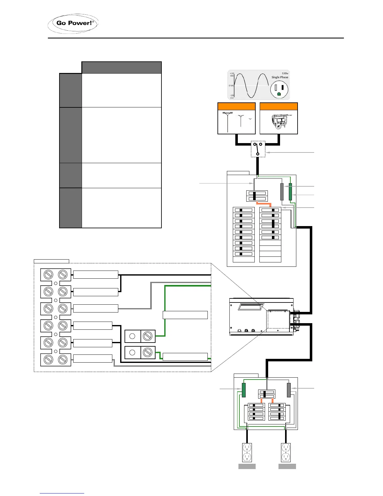
IN 1
AC Hot 1 from main panel
ACN-IN
AC Neutral from main panel
AC Ground
AC Ground from main panel
OUT 1
AC Live to sub panel
ACN-OUT
AC Neutral to sub panel
AC Ground
AC Ground to sub panel
Generator Power
120/240 VAC
IN 2
AC Hot 2 from main panel
IN 1
AC Hot 1 from main panel
ACN-IN
AC Neutral from main panel
OUT 1
AC Live to sub panel
ACN-OUT
AC Neutral to sub panel
IN 2
AC Hot 2 from main panel
50A @ 120VAC (Hot 1)
50A @ 120VAC (Hot 2)
Note: Loads must be correctly balanced between both
phases (Hot 1 and Hot 2) on the breaker panels in order to
6000W
50A @ 120VAC (Hot 1 + Hot 2)
ACN-IN (White)
AC Neutral Input
ACN-OUT (Black)
AC Neutral to sub panel
AC Power from Utility or
Generator
ACN-IN (White)
AC Neutral Input
ACN-OUT (Black)
AC Neutral to sub panel
Inverter/Charger Chassis Ground
Inverter/Charger Chassis Ground
Main Chassis (RV, Boat)
Earth Ground
ACN-IN (White)
AC Neutral Input
ACN-OUT (Black)
AC Neutral to sub panel
AC Power from Utility or
Generator
AC Neutral to AC Source Ground
Transfer Relay Connected
AC Neutral to Chassis
Ground Disconnected
AC Neutral to AC Source Ground
Transfer Relay Connected
AC Neutral to AC Source Ground
Transfer Relay Disconnected
AC Neutral to Chassis
Ground Connected
OUT 2
AC Live to sub panel
Maximum 50A Breaker
(single pole)
AC Ground
AC Ground from main panel
AC Ground
AC Ground to sub panel
OUT 2
AC Live to sub panel
Transfer Switch
(only required if using
a hardwired generator
Transfer Switch
(only required if using
a hardwired generator
Split Phase - ≤50 Amp Service
Install Option 1
Single Phase - 30> Amp Service
Inverter/Charger Chassis Ground
Inverter/Charger Chassis Ground
Notes:
* All previous converter/charger wiring must be disconnected from the
breaker panel. The IC Series is now used for battery bank charging.
Notes:
* All previous converter/charger wiring must be disconnected from the
breaker panel. The IC Series is now used for battery bank charging.
Inverter / Charger
Inverter/Charger Chassis Ground
Inverter/Charger Chassis Ground
.
3.6.7 AC WIRING 2 - Single Phase, 30A> Service, Single IN /Single OUT
INSTALLATION
 Loading...