gpelectric.com | [page 35]
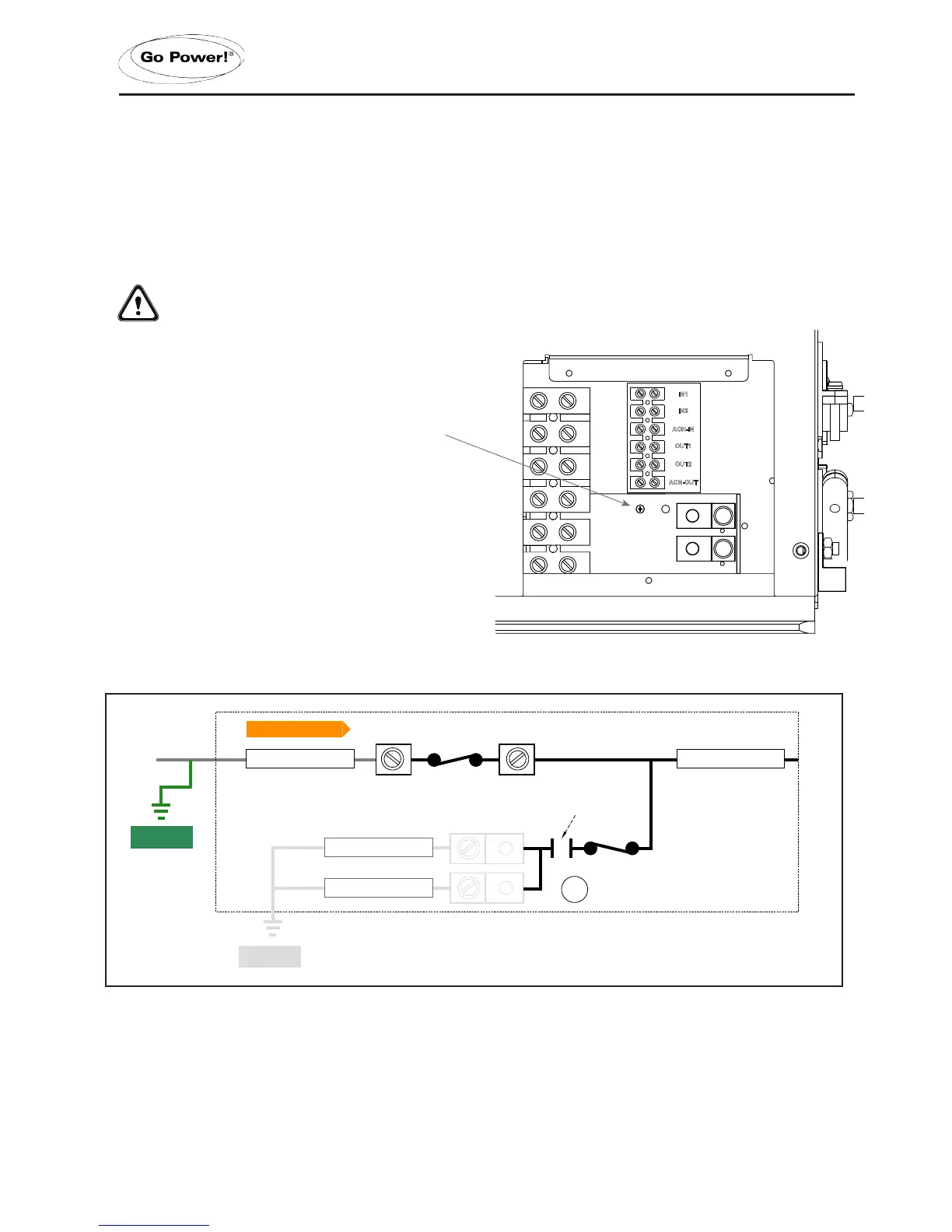
3.6.11 DISABLING THE NEUTRAL TO CHASSIS GROUND CONNECTION
The IC Series Inverter/Charger has the automatic neutral to ground switching feature enabled as a factory default setting. In
some installations this feature must be physically disabled by disconnecting the neutral to chassis ground connection. Please
consult your local code requirements to see if this feature must be physically disconnected.
The chassis ground connection (used for AC and DC grounding) on the outside of the Inverter/Charger should still be connected
to the system’s earth ground, even if the ground to neutral switching has been disabled.
WARNING: Disconnect all AC and DC power sources before working in the AC terminal wiring area.
1. Remove the AC cover plate.
2. Locate the two ground terminals. To the left of these connectors
is a Phillips screw. This screw must be un-screwed and removed
from the compartment. Keep this screw in a safe place.
3. Re-attach the AC cover plate.
IN1
IN2
OUT1
OUT2
ACN-OUT
ACN-IN
IN1
IN2
OUT1
OUT2
ACN-OUT
ACN-IN
size : 55x36.5mm
IN 1
AC Hot 1 from main panel
ACN-IN
AC Neutral from main panel
AC Ground
AC Ground from main panel
OUT 1
AC Live to sub panel
ACN-OUT
AC Neutral to sub panel
AC Ground
AC Ground to sub panel
Generator Power
120/240 VAC
IN 2
AC Hot 2 from main panel
IN 1
AC Hot 1 from main panel
ACN-IN
AC Neutral from main panel
OUT 1
AC Live to sub panel
ACN-OUT
AC Neutral to sub panel
IN 2
AC Hot 2 from main panel
50A @ 120VAC (Hot 1)
50A @ 120VAC (Hot 2)
Note: Loads must be correctly balanced between both
phases (Hot 1 and Hot 2) on the breaker panels in order to
6000W
50A @ 120VAC (Hot 1 + Hot 2)
ACN-IN (White)
AC Neutral Input
ACN-OUT (Black)
AC Neutral to sub panel
AC Power from Utility or
Generator
ACN-IN (White)
AC Neutral Input
ACN-OUT (Black)
AC Neutral to sub panel
Inverter/Charger Chassis Ground
Inverter/Charger Chassis Ground
Main Chassis (RV, Boat)
Earth Ground
ACN-IN (White)
AC Neutral Input
ACN-OUT (Black)
AC Neutral to sub panel
AC Power from Utility or
Generator
AC Neutral to AC Source Ground
Transfer Relay Connected
AC Neutral to Chassis
Ground Disconnected
AC Neutral to AC Source Ground
Transfer Relay Connected
AC Neutral to AC Source Ground
Transfer Relay Disconnected
AC Neutral to Chassis
Ground Connected
OUT 2
AC Live to sub panel
Maximum 50A Breaker
(single pole)
AC Ground
AC Ground from main panel
AC Ground
AC Ground to sub panel
OUT 2
AC Live to sub panel
Transfer Switch
(only required if using
a hardwired generator
Transfer Switch
(only required if using
a hardwired generator
Split Phase - ≤50 Amp Service
Install Option 1
Single Phase - 30> Amp Service
Inverter/Charger Chassis Ground
Inverter/Charger Chassis Ground
Notes:
* All previous converter/charger wiring must be disconnected from the
breaker panel. The IC Series is now used for battery bank charging.
Notes:
* All previous converter/charger wiring must be disconnected from the
breaker panel. The IC Series is now used for battery bank charging.
Inverter/Charger Inverter / Charger
Inverter/Charger Chassis Ground
Inverter/Charger Chassis Ground
 Loading...