gpelectric.com | [page 29]
INSTALLATION
7.3.2 ORDER OF CONNECTION
1. Connect the battery rst, then the solar panel and nally the load. Follow the “+” and “-” pole connection mode.
2. Connect the Master controller rst, then connect to the next Slave controller followed by the battery, solar panel and
lastly, the controller according to the ID.
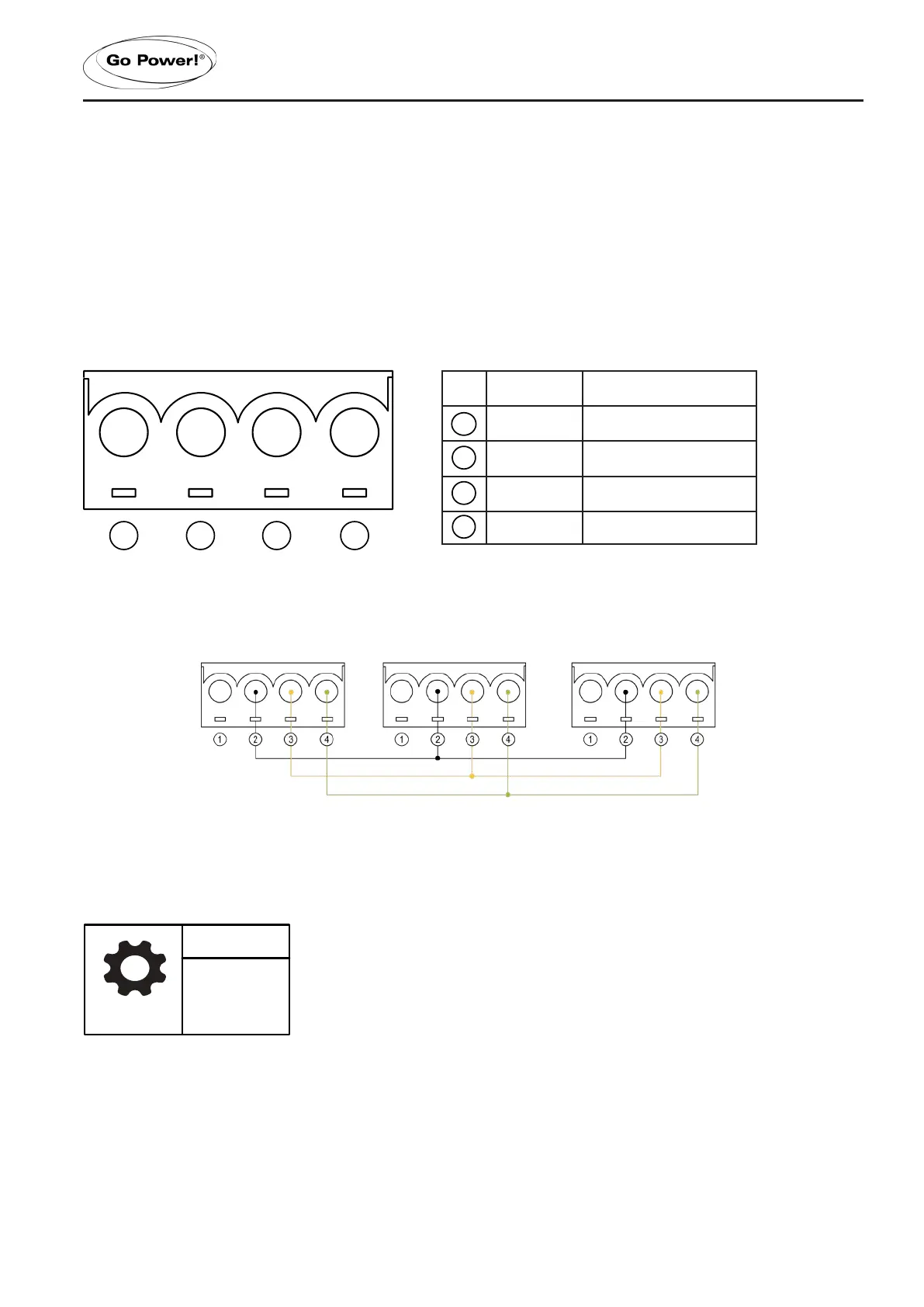
7.3.3 INTERFACE DEFINITION
RS485 INTERFACE
NO. DEFINITION PARALLEL OPERATION
12V
GND Black
D- Yellow
D+ Red
RS485 WIRING DIAGRAM (PARALLEL OPERATION)
7.3.4 PARAMETER SETTING
IN-SET MENU
1.
ADDRESS: the ID of the MASTER must be minimal, followed by the number from the machine to the large set.
For example, the MASTER ID is set to number 1, the SLAVE ID of the second controller is set to number 2 and the SLAVE
ID of a third one would be set to 3.
1 2 3 4
1
2
3
4
AUTO/SLD
BST : 14.4V
LVD : 11.0V
SET
 Loading...