gpelectric.com | [page 37]
In order to maintain the best long-term performance for the controller, conduct inspections twice a year using the following
points:
• Make sure the airow around the controller is unobstructed and remove any dirt or debris from the heat sink.
•
Check if the insulation layers of all exposed wires are damaged due to sun exposure, friction with other objects nearby,
dry rot, destruction of insects or rodents. If so, it may be necessary to repair or replace the wire.
•
Verify if indicators are consistent with the device operations. Please note to take corrective action for any malfunctions
or error indications.
•
Check all wiring terminals for corrosion, insulation damage, signs of high temperature or burning/discoloration. Tighten
terminal screws.
• Check for dirt, insects and corrosion and clean as required.
Warning: Danger, electric shock hazards! Make sure that all power supplies to the controller have been
disconnected before check or operation as above
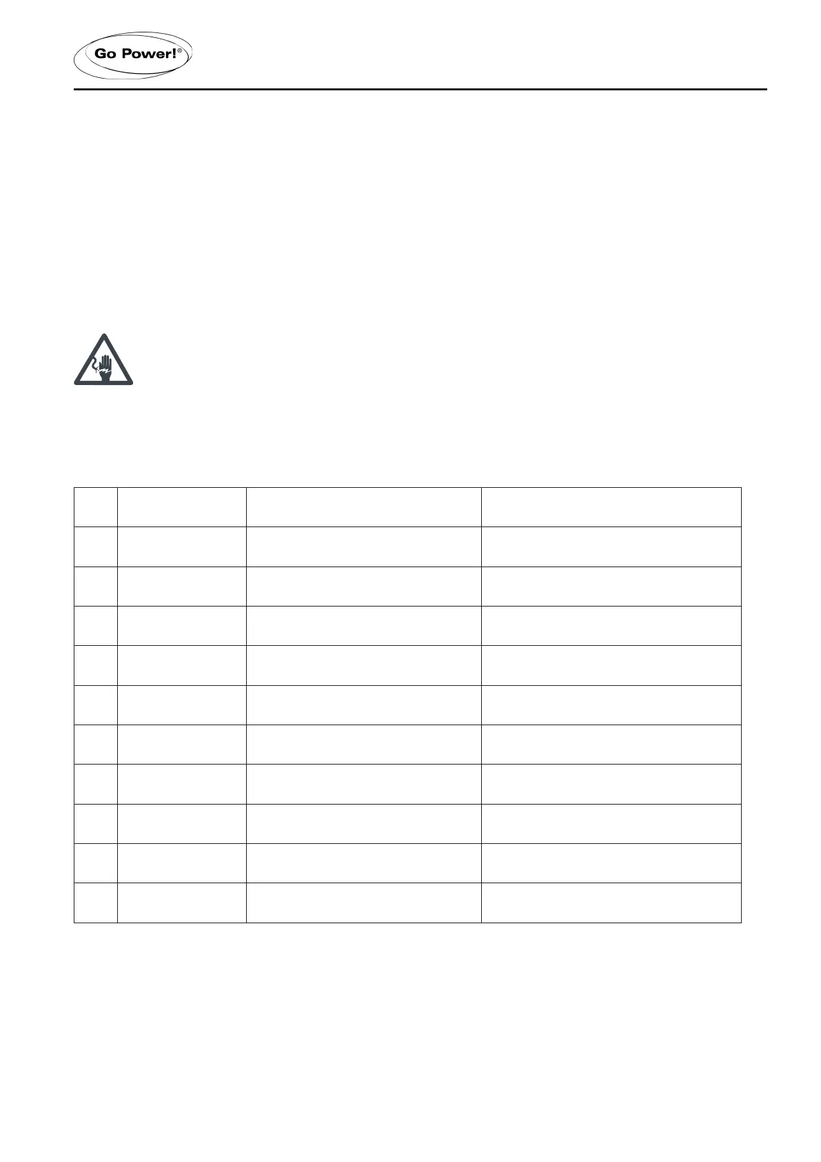
10.1 ERRORS AND WARNINGS
No. Error Display Description LED Indication
1 E0 No error ERROR indicator o
2 E1 Battery over-discharge
BAT indicator ashing slowly
ERROR indicator steady on
3 E2 System over-voltage
BAT indicator ashing quickly
ERROR indicator steady on
4 E3 Battery under-voltage warning ERROR indicator steady on
5 E4 Load short circuit
LOAD indicator ashing quickly
ERROR indicator steady on
6 E5 Load overloaded
LOAD indicator ashing quickly
ERROR indicator steady on
7 E6 Over-temperature inside controller ERROR indicator steady on
8 E7 Photovoltaic component overloaded ERROR indicator steady on
9 E8 Photovoltaic component over-voltage ERROR indicator steady on
10 E9
Photovoltaic component reversely con-
nected
ERROR indicator steady on
10 SYSTEM MAINTENANCE
 Loading...