Do you have a question about the golmar Nexa Modular G2+ and is the answer not in the manual?
| Brand | golmar |
|---|---|
| Model | Nexa Modular G2+ |
| Category | Intercom System |
| Language | English |
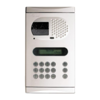
Exploded view of the Nexa Modular door panel assembly and its main components.
Details on the door panel's physical description and its constituent parts.
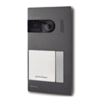
Description of the Video Module (EL632/G2+ SE, EL642/G2+) for video and audio systems.
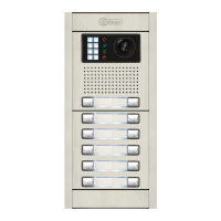
Description of the Button Module (EL610D) for various button configurations.
Details on the short connection cable for module interconnections.
Information about the RAP-610D connection cable for module interconnections.
Detailed description of the sound module's front and back views, including terminals.
Detailed description of the EL610D button module's front and back views, including DIP switches.
Guidance on correctly positioning the embedding box within the wall.
Instructions on preparing the wall opening for cable entry into the embedding box.
Steps for fitting the embedding box securely into the prepared wall opening.
Instructions on how to correctly mount the sound and button modules into the frame.
Procedure for securely attaching the door panel frame to the embedding box.
Guidance on connecting button modules using short cables within the same or different boxes.
Instructions for connecting button modules using the RAP-610D cable.
Setting call codes for buttons using DIP switches for video installations.
Detailed guide on setting DIP switches for double button module call codes.
Detailed guide on setting DIP switches for single button module call codes.
Continued guide on setting DIP switches for single button module call codes.
Setting call codes for buttons using DIP switches for audio-only installations.
Continued guide on setting DIP switches for single button module call codes for audio systems.
Setting DIP switches for double button module call codes in audio systems.
Continued DIP switch configuration for double button modules in audio systems.
Further DIP switch configuration for double button modules in audio systems.
Final DIP switch configurations for double button modules in audio systems.
DIP switch settings for single button modules in specific terminal configurations.
Continued DIP switch settings for single button modules in specific terminal configurations.
Further DIP switch settings for single button modules in specific terminal configurations.
Final DIP switch settings for single button modules in specific terminal configurations.
Explanation of the DIP switch functions on the sound module for configuration.
Details on the audio level jumper for controlling vocal synthesis and tones volume.
Explanation of the door panel lighting LEDs for low light conditions.
Visual indicators on the door panel for hearing impaired users.
Audible voice messages from the door panel for visually impaired users.
Audible tones emitted by the door panel for different call states.
Details on connecting external P1 and P2 buttons to the sound module.
Connecting the sound module to the CD-NEXA/G2+ digital converter module.
Connecting the sound module to EL3002 illumination modules via CD-NEXA/G2+ converter.
Configuring vocal synthesis language or tones mode via DIP switches.
Procedure to change call codes for P1 and P2 buttons using DIP switches.
Making final adjustments to the system, including telecamera positioning.
Steps for securely closing the door panel frame after wiring and configuration.
Guidance on inserting labels into the button holder windows.
Step-by-step guide for mounting modules into a single door panel frame.
Instructions for mounting modules in a double door panel configuration.
Final steps to close and secure the door panel to the embedding box.
Procedure for installing the lock release mechanism, including drill bit sizes.
Overview of the FA-G2+ power supply unit, its specifications and components.
Guidelines for safely installing the FA-G2+ power supply unit.
Wiring diagram for an audio system with many terminals and a DC lock release.
Wiring for an audio system with multiple risers and no distributors.
Wiring for a video system with ART 4 monitors and D4L distributors.
Wiring for a video system with ART 4 monitors and D2L distributors.
Wiring for mixed video and audio systems with D4L distributors.
Wiring for a video system with ART 7 monitors and D4L distributors.
Wiring for a video system with ART 7 monitors and D2L distributors.
Wiring for mixed video/audio systems with ART 7 and ART 1, using D4L distributors.
Wiring for video systems with ART 7W monitors and D4L distributors.
Wiring for video systems with ART 7W monitors and D2L distributors.
Wiring for mixed ART 7W and ART 1 systems with D4L distributors.
Wiring for a smaller video system with ART 7 monitors, no distributors.
Wiring for ART 7 systems with 2 risers and D2L distributors.
Wiring for ART 7 systems with 4 risers and D4L distributors.
Wiring for ART 7 IN-OUT systems with 4 risers, no distributors.
Wiring for 1-building systems with multiple risers and DC lock release.
Wiring for 1-building systems with multiple risers and AC lock release.
Wiring for systems with 2 access panels and DPM-G2+ distributor.
Wiring for systems with 4 access panels and DPM-G2+ distributor.
Diagrams for connecting Golmar DC and AC lock releases with external buttons.
Example of a riser installation with 2 risers and 1 access panel for various monitor types.
Example of a riser installation with 4 risers and 1 access panel for various monitor types.
Example of asymmetric riser installation with 4 risers and 1 access panel.
Continued example of asymmetric riser installation with 4 risers and 1 access panel.
Example of IN-OUT riser installation without distributors for 4 risers.
Guide on connecting an external analogue CCTV camera to the door panel.
Instructions for safely cleaning the door panel without causing damage.