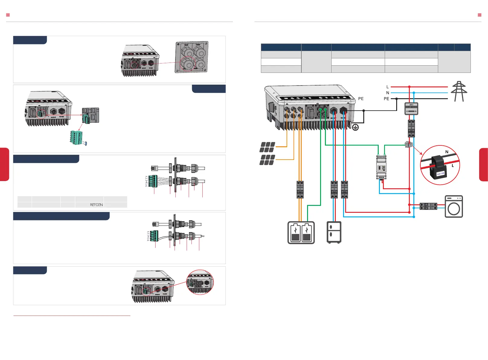
Please select Breaker according to the specification below
2.6 EARTH FAULT ALARM CONNECTION
1. Put the cable through the plate as shown in Pic 31.
2. Wiring from the No. 5 and 6 holes respectively.
Step 3-1 For DRED
Step 3-2 For Remote Shutdown
15
INSTALLATION INSTRUCTIONS
MAMUAL OPERATION
1. Put DRED cable through the plate as shown in Pic 30.
2. Connect DRED cable on the 6-pin terminal.
The function of each connection position as below:
Screw this plate off from inverter (Pic 28).
Connect DRED terminal to the right position onto
the inverter (Pic 32).
1. Plug out the 6-pin terminal and dismantle
the resistor on it (Pic 29).
2. Plug the resistor out, leave the 6-pin terminal
for next step.
GoodWe EH series inverter complies with IEC 62109-2 13.9. Fault indicator LED on
inverter cover will light up and the system will email the fault information to customer.
Inverter should be installed at eye level for convenient maintenance.
Detailed connection of DRED device is shown below:
1.For batteries with attached breaker, the external DC breaker is not necessary.
2.Direction of the CT cannot be connected in reverse, please follow House (K)→Grid (L)
direction to do the connection.
3.For Battery-Ready inverters, there is no need to route between the battery and the
inverter before activating the battery function.
4.For Battery-Ready inverters without the Smart Meter, there is no need to route them
before purchasing a Smart Meter.
For Spain Grid code, the output max. apparent power of GW6000-EH is 6KVA and will be less than
5kVA exported to grid limited by CT controller and power meter.
If the generation facility to be connected to the supply network with more than 5 kVA power in
single phase, connection of the facility to the network shall be three-phase with an imbalance
between phases of less than 5kW.
WIRING SYSTEM FOR EH SERIES HYBRID INVERTER
GW3600-EH
GW5000-EH
GW6000-EH
50A/230V AC breaker
50A/230V AC breaker
63A/230V AC breaker
32A/230V AC breaker
32A/230V AC breaker
32A/230V AC breaker
40A/600V
DC breaker
Depends on
household
loads
④③②① ⑤
House → Grid
Grid
PV Strings
Reset
SMART METER
USB
②
AC Breaker
⑤
AC Breaker
Power Meter
CT [2]
③AC Breaker
To Battery Cable
To Smart Meter
Smart Meter [4]
①
DC Breaker
≥40A [1]
Back-Up LoadBattery[3]
On-Grid Load
④
AC Breaker
Step 1
Step 2
Step 4
Note: DRED device should be connected
through“DRED port" as the figure shows.
Note: the 6- Pin terminal in the inverter has the
same function of DRED device. Please leave it on
the inverter if no external device connected.
Pic 28
Pic 29
Pic 30
Pic 31
Pic 32
Screw
Screw
Cap
Cable
Single hole
seal ring
Nut
The
Insulator
RS485
communication board
Screw
Screw
Cap
Cable
Single hole
seal ring
Nut
The
Insulator
RS485
communication board
NO 1 2 3 4 5 6
Function DRM1/5 DRM2/6 DRM3/7 DRM4/8 COM/DRMO
Grid
 Loading...