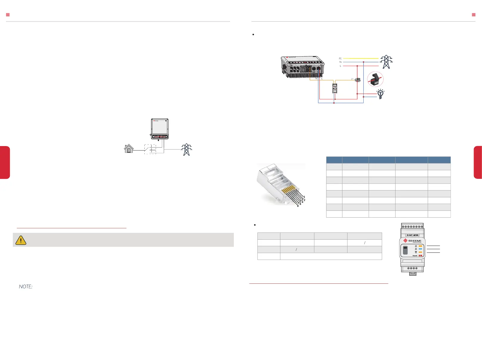
2. One Smart Meter can only be used for one EH inverter.
3. CT must be connected on the same direction as the CT indicated.
DRED is used for Australia and New Zealand installation (also used as remote shutdown
function in European countries), in compliance with Australia and New Zealand safety
requirements( or European countries). And DRED device is not provided by GoodWe.
13
INSTALLATION INSTRUCTIONS
MAMUAL OPERATION
The Smart Meter with CT in GoodWe product box is compulsory for EH system installation,
used to detect grid voltage and current direction and magnitude, further to instruct the
operation condition of EH inverter via RS485 communication.
Accepted loads as below:
• Inductive Load: 1.5P non-frequency conversion air-conditioner can be connect to
back-up side. Two or more non-frequency conversion air-conditioner connect to
back-up side may cause UPS mode unstable.
• Capacitive Load: Total power <= 0.6 x nominal power of model. (Any load with high
inrush current at start-up is not accepted.)
• For complicated application, please contact GoodWe's after service.
Declaration For Back-Up Loads
EH series hybrid inverters are able to supply over load output at its’ Back-Up. For
details please refer to the technical parameters of EH series inverter (4.3 section). And
the inverter has self-protection derating at high ambient temperature.
Note:
For a convenient maintenance, an DP3T
support could be installed on Back-Up and
On-Grid side. Then it is adjustable to
support load by Back-Up or by grid or just
leave it there (Pic 26).
Declaration For Back-Up Overload Protection
Inverer will restart itself as overload protection happens. The preparation time for
restarting will be longer and longer (max one hour) if overload protection repeats. Take
following steps to restart inverter immediately.
• Decrease Back-Up load power within max limitation.
• On PV Master →Adcanced Setting → Click “Reset Back-Up Overload History”
Make sure AC cable is totally isolated from AC power before connecting Smart Meter & CT.
[6]
Smart Meter & CT Connection Diagram (Pic 27)
Smart Meter LED Indications
2.4.4 SMART METER & CT CONNECTION
If you buy a Battery-Ready inverter without the Smart Meter, it is not necessary to view this
section.
1. The Smart Meter and CT is well configured, please do not change any setting on Smart Meter;
2.5 DRED & REMOTE SHUTDOWN CONNECTION
NOTE:
1. Please use the Smart Meter with CT in GoodWe product box.
2.CT cable is 3m as default, could be extended to max 5m.
3. Smart Meter communication cable (RJ45) is attached on the inverter ("To Smart Meter " cable), could
be extended to max 100m, and must use standard RJ45 cable and plug, as below:
1:Load is supplied from Back-Up side
2:Load is isolated
3:Load is supplied from grid side
Back-up
Pic 26
Pic 27
“To Smart Meter”
Grid Side
Grid
Load
Position
1
Orange&white 485_A2
485_A1
485_A
485_A
485_A1
485_B2 485_B1
485_B
485_B
485_B1
NC
NC
NC
NC
NC
NC
NC
NC
NC
NC
NC
NC
CAN_H
CAN_L
Green&white
Green
Blue&white
Blue
Brown&white
Brown
Orange
2
3
4
5
6
7
8
Color
BMS Function Smart Meter Function RS485
OFF
Not working Working
Importing Exporting
POWER
ENERGY
COM
ON Blinking
Blink one time when it transfer data to inverter
POWER
ENERGY
COM
 Loading...