INTRODUCTION
• SAFETY WARNING
03
INTRODUCTION
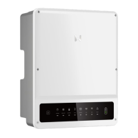
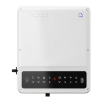
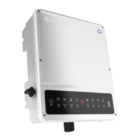
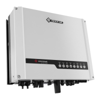
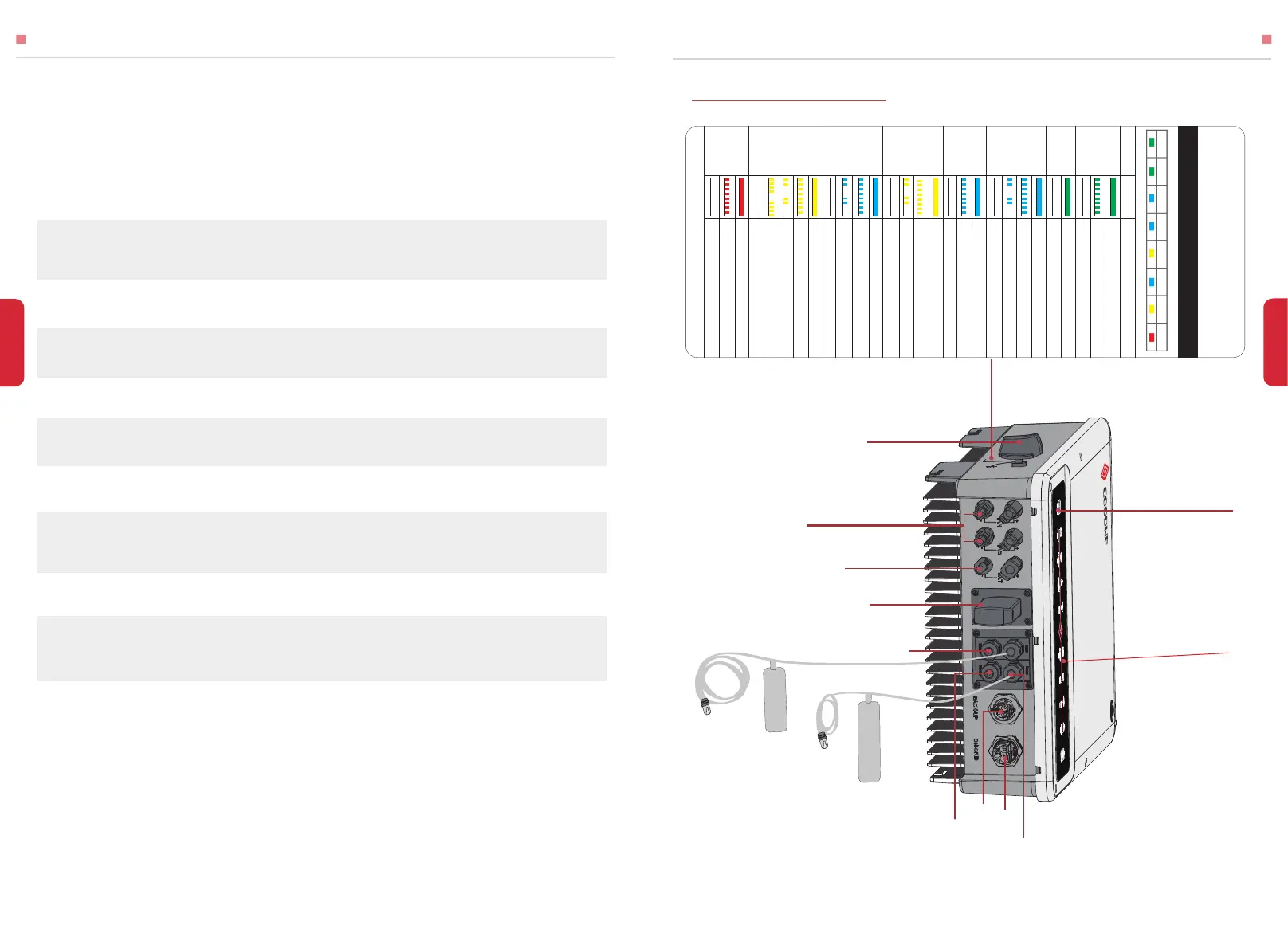
1.3 PRODUCT OVERVIEW
04
Prohibit to insert or pull the AC and DC terminals when the inverter is running.
Before any wiring connection or electrical operation on inverter, all battery and AC power
must be disconnected from inverter for at least 5 minutes to make sure inverter is totally
isolated to avoid electric shock.
The temperature of inverter surface might exceed 60℃ during working, so please make sure
it is cooled down before touching it, and make sure the inverter is untouchable for children
Do not open inverter cover or change any components without GoodWe’s authorization,
otherwise the warranty commitment for the inverter will be invalid.
Usage and operation of the inverter must follow instructions in this user manual, otherwise
the protection design might be useless and warranty for the inverter will be invalid.
Appropriate methods must be adopted to protect inverter from static damage. Any damage
caused by static is not warranted by GoodWe.
PV negative (PV-) and battery negative (BAT-) on inverter side is not grounded as default
design. Connecting PV- or BAT- to EARTH are strictly forbidden.
PV modules used on the inverter must have an IEC61730 class A rating, and the total
open-circuit voltage of PV string/array is lower than the maximum rated DC input voltage of
the inverter. Any damage caused by PV over-voltage is beyond warranty.
The inverter, with built-in RCMU, will exclude possibility of DC residual current to 6mA, thus
in the system an external RCD (type A) can be used(≥30mA).
In Australia, the inverter internal switching does not maintain neutral integrity, which must
be addressed by external connection arrangements like in the system connection diagram
for Australia on page 16.
In Australia, output of Back-Up side in switchbox should be labeled ‘Main switch UPS
supply’, the output of normal load side in switch box should be labeled ‘main switch
inverter supply’.
Any installation and operation on hybrid inverter must be performed by qualified electri-
cians, in compliance with standards, wiring rules or requirements of local grid authorities
or companies (like AS 4777 and AS/NZS 3000 in Australia).
Wi-Fi Box
LED Label
On-Grid Port
DC Switch
PV Terminals
Battery Terminals
Back-Up Port
DRED
Meter
Wi-Fi Reset
Reserved
RS485
To Smart Meter
Smart Meter Communication Cable
BMS Communication Cable
To Battery
SYSTEM
INDICATOR STATUS EXPLANATION
BACK-UP BATTERY GRID ENERGY
COM WiFi FAU LT
HYBRID LED INDICATORS
SYSTEM
BACK-UP
BATTERY
GRID
ENERGY
COM
WiFi
FA U LT
ON = SYSTEM IS READY
BLINK = SYSTEM IS STARTING UP
OFF = SYSTEM IS NOT OPERATING
ON = BACK-UP IS READY / POWER AVAIL ABLE
OFF = BACK-UP IS OFF / NO POWER AVAILABLE
ON = BATTERY IS CHARGING
BLINK 1 = BATTERY IS DISCHARGING
BLINK 2 = BATTERY IS LOW / SOC IS LOW
OFF = BATTERY IS DISCONNECTED / NOT ACTIVE
ON = GRID IS ACTIVE AND CONNECTED
BLINK = GRID IS ACTIVE BUT NOT CONNECTED
OFF = GRID IS NOT ACTIVE
ON = CONSUMING ENERGY FROM GRID / BUYING
BLINK 1 = SUPPLYING ENERGY TO GRID / ZEROING
BLINK 2 = SUPPLYING ENERGY TO GRID / SELLING
OFF = GRID NOT CONNECTED OR SYSTEM NOT
OPERATING
ON=BMS AND METER COMMUNICATION OK
BLINK 1= METER COMMUNICATION OK, BMS
COMMUNICATION FAIL
BLINK 2= BMS COMMUNICATION OK, METER
COMMUNICATION FAIL
OFF= BMS AND METER COMMUNICATION FAIL
ON = WiFi CONNECTED / ACTIVE
BLINK 1 = WiFi SYSTEM RESETTING
BLINK 2 = WiFi NOT CONNECT TO ROUTER
BLINK 4 = WiFi SERVER PROBLEM
OFF = WiFi NOT ACTIVE
ON = FAULT HAS OCCURRED
BLINK = OVERLOAD OF BACK-UP OUTPUT /
REDUCE LOAD
OFF = NO FAULT
 Loading...