21
User Manual V1.0-2022-01-17
06 Electrical Connection
6 Electrical Connection
6.1 Safety Precautions
NOTICE
• Wear personal protective equipment like safety shoes, safety gloves, and insulating gloves
during electrical connections.
• All electrical connections should be performed by qualied professionals.
• Cable colors in this document are for reference only. The cable specications should meet
local laws and regulations.
DANGER
• Disconnect the DC switch and the AC output switch of the inverter to power o the
equipment before any electrical connections. Do not work with power on. Otherwise, an
electric shock may occur.
• Perform electrical connections in compliance with local laws and regulations. Including
operations, cables, and component specications.
• If the tension is too large, the cable may be poorly connected. Reserve a certain length of the
cable before connecting it to the inverter cable port.
WARNING
• The PE cable connected to the enclosure of the inverter cannot replace the PE cable
connected to the AC output port. Both of the two PE cables must be securely connected.
• Make sure that all the grounding points on the enclosures are equipotential connected
when there are multiple inverters.
• To improve the corrosion resistance of the terminal, it is recommended to apply silica gel or
paint on the ground terminal after installing the PE cable.
• The PE cable should be prepared by customers. Recommended specications:
• Type: single-core outdoor copper cable.
• Conductor crosssectional area S≥10mm
2
(GW8000-SDT-20, GW10K-SDT-20, GW12K-
SDT-20, GW12KLV-SDT-20, GW15K-SDT-20, GW17K-SDT-20, GW20K-SDT-20).
• Conductor crosssectional area S≥4mm
2
(Other models).
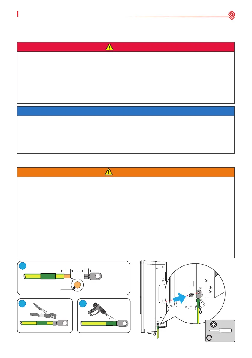
6.2 Connecting the PE Cable
L=L1+(1~2)mm
L1
S
M5
1.2~2N·m
1
2
3
 Loading...