Temperature Control Diagnostic Codes
3A1570V 11
Temperature Control Diagnostic Codes
Temperature control diagnostic codes appear on
temperature display.
These alarms turn off heat. E99 clears automatically
when communication is regained. Codes E03 through
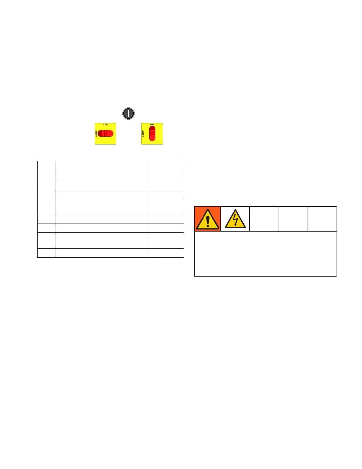
E06 can be cleared by pressing . For other codes,
turn main power OFF then ON to
clear.
NOTE: For hose zone only, if FTS is disconnected at
startup, display will show hose current 0A.
E01: High fluid temperature
Causes of E01 Errors
• Thermocouple A or B (361) senses a fluid
temperature above 230°F (110°C).
• Fluid temperature sensor (FTS) senses a fluid
temperature above 230°F (110°C).
• Overtemperature switch (359) senses a fluid
temperature above 230°F (110°C) and opens. At
190°F (87°C) the switch closes again.
• Thermocouple A or B (361) fails, is damaged, is not
touching the heater element (358), or has a poor
connection to the temperature control module.
• Overtemperature switch (359) fails in the open
position.
• The temperature control module fails to turn off any
heat zone.
• Zone power wires or thermocouples are switched
from one zone to another.
• Failed heater element where thermocouple is
installed.
• Loose wire
• Jumper wire covered in heat shrink in the wiring
harness near the single over temperature switch
connectors on the heater, is loose or incorrectly
wired
Checks
Check which zone is displaying the E01 error.
1. Check that connector B is firmly plugged into
temperature control module (see F
IG
. 6, page 29).
2. Clean and re-plug connections.
3. Check connections between the temperature
control module and overtemperature switch (359),
and between temperature control module and
thermocouples A and B (361) or FTS (21)
[depending on which zone is displaying E01]. See
Table 2, page 29. Ensure that all wires are securely
connected to connector B.
4. Remove connector B from temperature control
module, and check continuity of overtemperature
switch, thermocouples A and B, or FTS by
measuring resistance across the pins on the plug
end; see Table 1, page 12.
Code Code Name Alarm Zone
01 High fluid temperature Individual
02 High zone current Individual
03 No zone current Individual
04 FTS or thermocouple
disconnected
Individual
05 Control board over temperature Individual
06 Communication cable unplugged Individual
30 Momentary loss of
communication
All
99 Loss of communication All
Troubleshooting this equipment requires access to
parts that may cause electric shock or other serious
injury if work is not performed properly. Have a
qualified electrician perform all electrical
troubleshooting. Be sure to shut off all power to the
equipment before repairing.

 Loading...