Temperature Control Diagnostic Codes
12 3A1570V
NOTE: Before doing the following checks, note which
zone (A, B, FTS, or all) has high fluid temperature.
5. Verify fluid temperature, using an external
temperature sensing device.
6. If temperature is too high (sensor reading is
229°F [109°C] or above), check if thermocouples A
and B are damaged, or not contacting the heater
element. See Thermocouple, page 33.
7. To test that temperature control module turns off
when equipment reaches temperature setpoint:
a. Set temperature setpoints far below displayed
temperature.
b. Turn zone on. If temperature rises steadily,
power module is failing.
c. Verify by swapping with another power module.
See Replacing Temperature Control
Assembly Modules, page 30.
d. If the swapped module does not fix the problem,
the power module is not the cause.
8. Verify continuity of heater elements with an
ohmmeter, see Primary Heater, page 31.
E02: High zone current
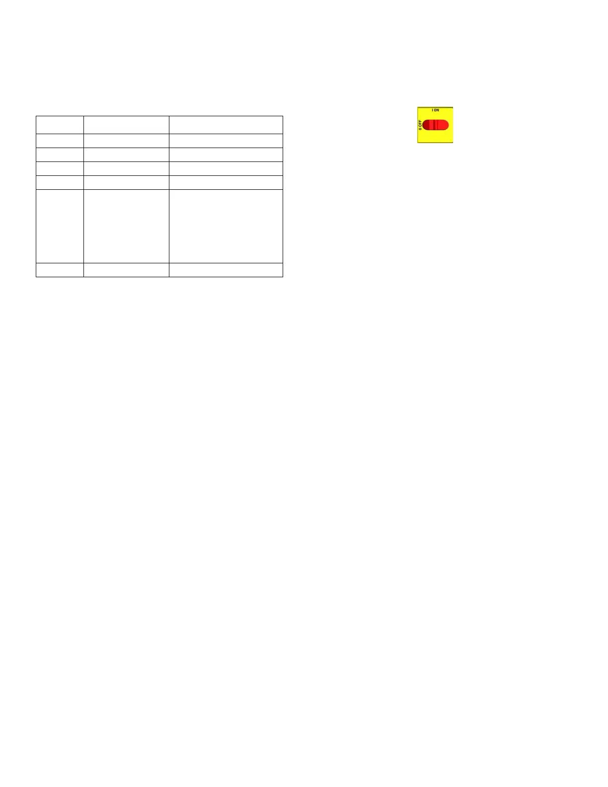
1. Turn main power OFF .
2. Follow the Pressure Relief Procedure, page 15.
NOTE: Disconnect whip hose.
3. Disconnect hose connector (D) at Reactor.
4. Using an ohmmeter, check between the two
terminals of the connector (D). There should be no
continuity.
5. Exchange zone module with another one. Turn
zone on and check for error (see Replacing
Temperature Control Assembly Modules, page
30). If error disappears, replace faulty module.
For hose zone: If error still occurs, perform
Transformer Primary Check and Transformer
Secondary Check, starting on page 37.
NOTE: When there is a high current error, the LED on
that zone’s module will turn red while the error is
displayed.
E03: No zone current
1. Check for tripped circuit breaker inside electrical
cabinet or at power source for that zone. Replace
circuit breaker if it trips habitually.
2. Check for loose or broken connection at that zone.
3. Exchange zone module with another one. Turn
zone on and check for error (see Replacing
Temperature Control Assembly Modules, page
30). If error disappears, replace faulty module.
4. If E03 occurs for all zones, the 238CR contactor
may not be closing. Verify wiring from heater control
to contactor coil.
a. Hose zone: test hose continuity, page 34.
b. Perform Transformer Primary Check and
Transformer Secondary Check, starting on
page 37.
NOTE: When a no current error occurs, the LED on this
specific zone’s module turns red when the error is
displayed.
Table 1: Sensor Connector Continuity
Checks
Pins Description Reading
1 & 2 OT switch nearly 0 ohms
3 & 4 Jumpered nearly 0 ohms
5 & 6 Thermocouple A 4-6 ohms
8 & 9 Thermocouple B 4-6 ohms
11 & 12 FTS approximately 35
ohms per 50 ft (15.2
m) of hose, plus
approximately 10
ohms for FTS at 70°F
(21°C)
10 & 12 FTS open

 Loading...