Repair
34 3A1570V
Overtemperature Switch
1. Turn main power OFF . Disconnect power
supply.
2. Follow the Pressure Relief Procedure, page 15.
3. Wait for heaters to cool.
4. Remove heater shroud.
5. Disconnect one leadwire from overtemperature
switch (359), F
IG
. 8, page 33. Test across switch
with ohmmeter. Resistance must be approximately
0 ohms.
6. If switch fails test, remove wires and screws. Dis-
card failed switch. Apply thermal compound
110009, install new switch in same location on
housing (351), and secure with screws (311).
Reconnect wires.
NOTE: If wires need replacement, disconnect
temperature control module. See Table 2, page 29 and
F
IG
. 6, page 29.
Heated Hose
Refer to the heated hose manual for hose replacement
parts.
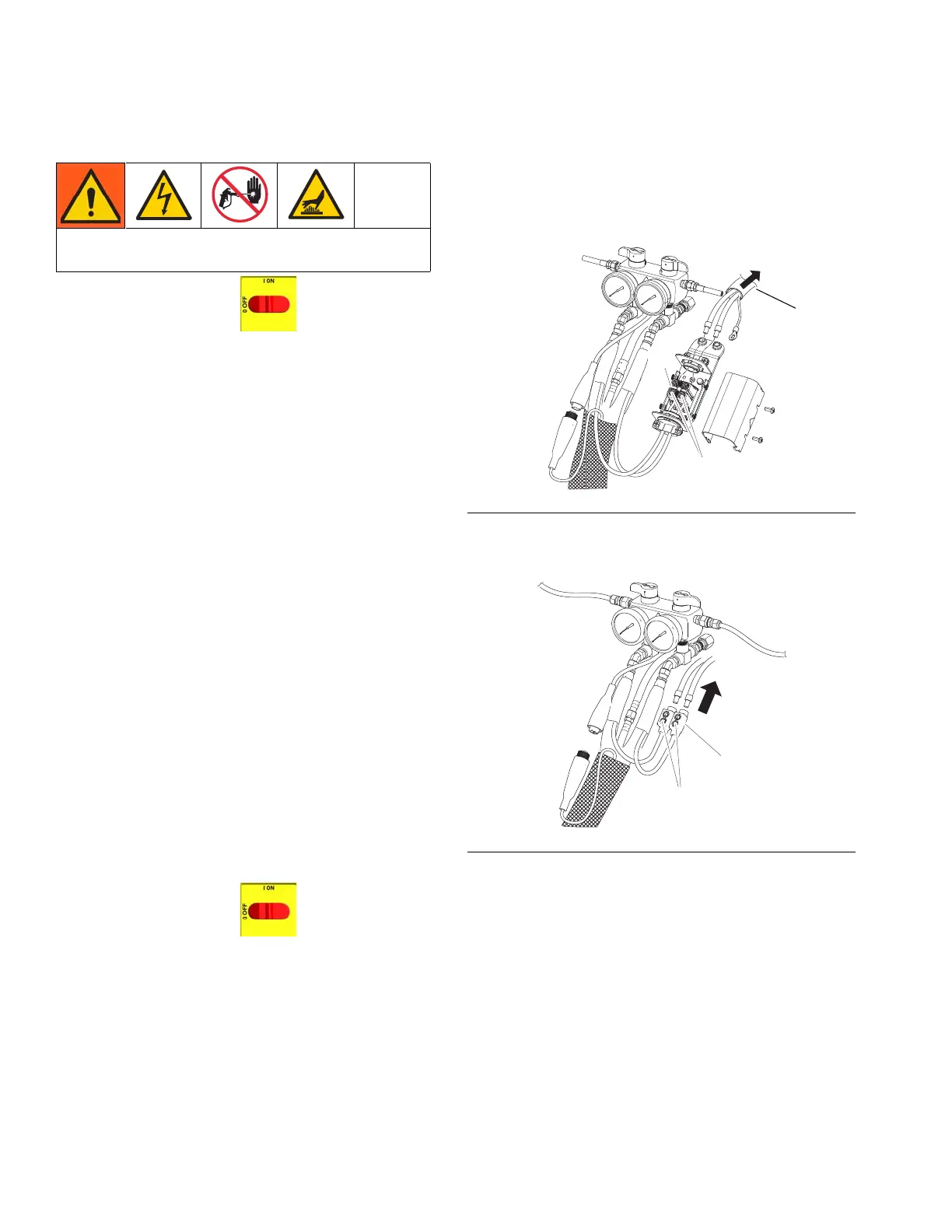
Check Hose Power Connectors
1. Turn main power OFF . Disconnect power
supply.
2. Follow the Pressure Relief Procedure, page 15.
NOTE: Whip hose must be connected.
3. Disconnect Reactor power harness (PH) from hose
termination box terminal block (TB).
4. For Series A only: Disconnect hose connector (D)
at Reactor.
5. Using an ohmmeter, check between the two
terminals of the connector (TEST). There should be
continuity.
6. If hose fails test, retest at each length of hose,
including whip hose, until failure is isolated.
Read Warnings on page 5. Wait for heater to cool
before repairing.
F
IG
. 9
F
IG
. 10
WLD

 Loading...