Temperature Control Diagnostic Codes
10 309574L
Temperature Control Diagnostic Codes
Temperature control diagnostic codes E01 through E05
appear on temperature display.
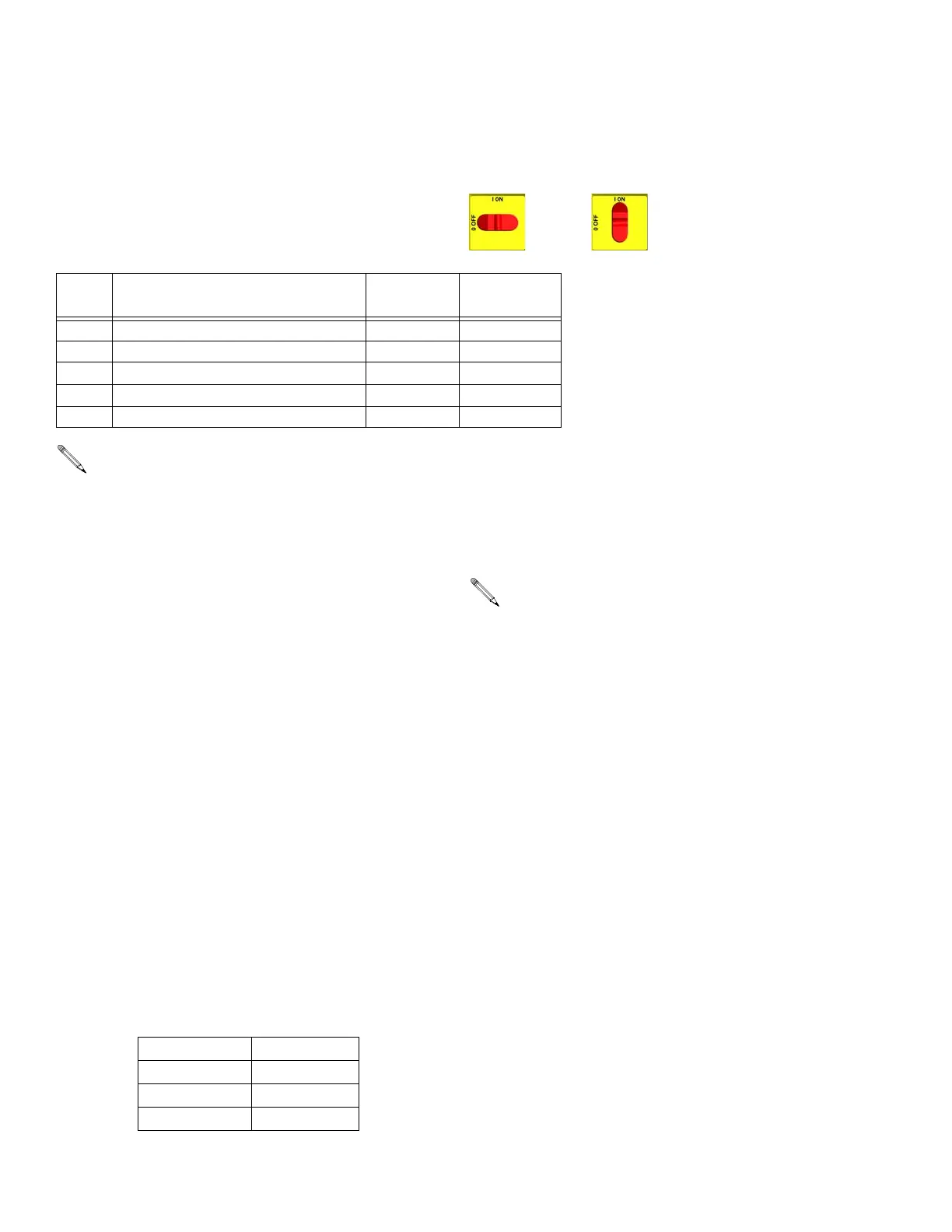
These alarms turn off heat. Turn main power OFF
then ON to clear.
E01: High fluid temperature
1. Using an external temperature-sensing device,
check to see if you really do have high tempera-
tures.
2. Check connections between temperature control
board and heater overtemperature switches, page
42.
3. Make sure all of the wires are securely connected
into connector J1.
4. Check temperature sensors, page 41.
5. Check temperature sensor is contacting heater ele-
ment, page 41.
If you do not have high temperature (A
temp reading below 190° F):
1. Make sure connector J1 is firmly plugged into the
heater control board.
2. Check continuity of the over-temperature switches
and the "A" and "B" temperature sensors by remov-
ing the J1 plug from the temperature control board
socket. On the plug end check the resistance:
If you do have a high temperature:
1. Note what zone (“A”, “B”, or both) is exhibiting the
high temperature condition.
2. Check resistance of the "A" and "B" temperature
sensors. Remove the J1 plug from the temperature
control board socket. Refer to Table 4, page 38.
Resistance across pins 7 and 8 = 4 - 6 ohms. Resis-
tance across pins 10 and 11 = 4 - 6 ohms.
3. Check temperature sensor is contacting heater ele-
ment, page 41.
4. Check if the heater control board turns off when the
unit hits the set point temperature.
• With power off, remove the wire nuts on the
back of the unit leading to the heater, attach the
leads of an A/C volt meter to the wires, and tape
them off so they can’t be touched or shorted.
• Set the “A” and “B” set point below the ambient
temperature, and turn the heat zones on. The
red light above each zone should blink and the
voltmeter should read little to no voltage. Mea-
suring line voltage while the red light is blinking
would indicate that the relay on the heater con-
trol board has failed. In this case, replace the
heater control board.
Code
No.
Code Name Alarm Zone Corrective
Action page
01 High fluid temperature Individual 10
02 High hose current Hose only 11
03 No hose current with hose heater on Hose only 11
04 FTS or thermocouple not connected Individual 13
05 Board overtemperature All 14
For hose zone only, if FTS is disconnected at startup, display will show hose current 0A.
Pins 1 & 2 ~ 0 Ω
Pins 3 & 4 ~ 0 Ω
Pins 7 & 8 4 - 6 Ω
Pins 10 & 11 4 - 6 Ω
You will need to cool the unit down to be able to
do any testing. Using your feed pumps to move
cool material into the Reactor can do this.

 Loading...