Temperature Control Diagnostic Codes
309574L 13
4. Check 50A (806) and 20A (817A) circuit breakers,
page 32.
5. Test current sensor continuity, page 46.
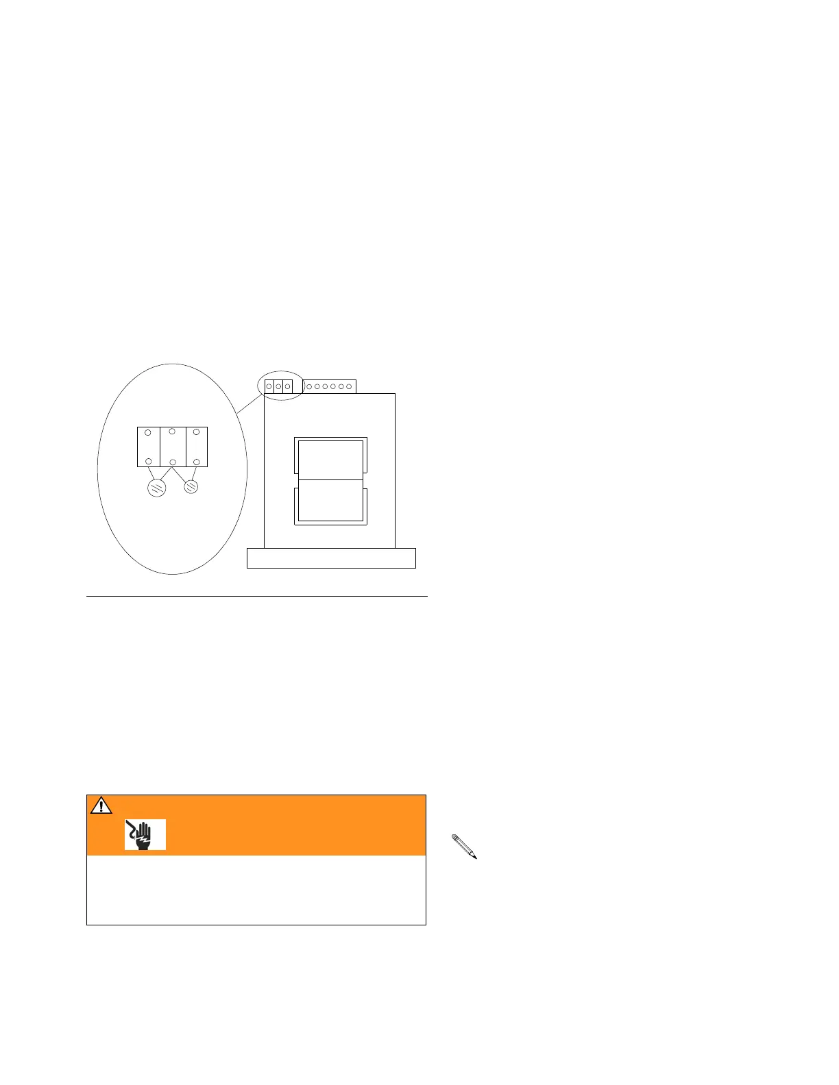
6. With the main power off, test the In-rush current lim-
iter (“black lollipop”), by doing a continuity measure-
ment across the two leads on the In-rush limiter,
located on the left hand side of the transformer. See
F
IG. 3. (There are two different orientations of the
In-rush limiter, both located on the left hand side of
the transformer). You should have continuity; gener-
ally the measurement should read between 5 – 20
ohms. If you don’t have continuity, the In-rush cur-
rent limiter bad – replace the In-rush limiter.
7. Complete Transformer Primary check:
a. Make sure everything is reconnected, including
the hose.
b. Turn the main power on.
c. Adjust the hose heat set point below the ambi-
ent hose temperature.
d. Turn the hose heat on.
e. Carefully measure the voltage across the two
wires of the red surge suppressor.
If you do not measure line voltage, the Temperature
Control Board is bad – replace the Temperature Control
Board.
8. Complete Transformer Secondary Check, page
49.
9. Perform SCR circuit check, page 44.
E03 (no lollipops)
Do steps in order. Do not skip any step.
1. Check 50A (806) and 20A (817A) circuit breakers,
page 32.
2. Check hose connectors for broken electrical con-
nection, page 43.
3. Do Transformer Secondary Check, page 48.
4. Test wire harness continuity.
5. Test complete hose continuity, page 43.
6. Test temperature control board to transformer wire
harness continuity, page 38.
7. Test transformer wire harness continuity, page 46.
8. Test current sensor continuity, page 46.
9. (380 V Only) Do In-rush current limiter check, page
46.
10. Do Transformer Primary Check, page 48.
11. Perform SCR circuit check, page 44.
E04: Fluid Temperature
Sensor (FTS) or “A” or “B”
thermocouple not
connected.
“A” and “B” side thermocouple assemblies:
1. Check the electrical connections at the temperature
control board. Refer to Table 4, page 38 and Figure
10, page 35.
F
IG. 3
WARNING
Read warnings, page 6. Step e measures line voltage
and should be done by a qualified electrician. If work is
not performed properly it may cause electric shock or
other serious injury.
Tra n sfo r me r
Front of
Black
Red
Terminal Block
Trans fo r m e r
The display that is showing the E04 error is the
zone that is seeing the error.

 Loading...