Repair
309574L 33
Electric Motor
Removal
2. Relieve pressure, page 9.
3. Remove drive housing/pump assemblies, page 28.
4. Disconnect motor cables as follows:
a. Refer to electrical diagrams. Motor control
board is on right side inside cabinet, see page
34.
b. Unplug motor power harness from connector J4
on board. See F
IG. 10, page 35.
c. Unplug 3-pin connector J7 from board.
d. Thread cables through top of cabinet to free
motor.
5. Remove screws holding motor to cabinet. Lift motor
off unit.
Installation
1. Place motor on unit. Thread motor cables into cabi-
net and into bundles as before. See electrical dia-
grams.
2. Fasten motor with screws.
3. Plug 3-pin connector J7 to board.
4. Plug motor power harness to connector J4 on
board.
5. Install drive housing/pump assemblies, page 28.
6. Return to service.
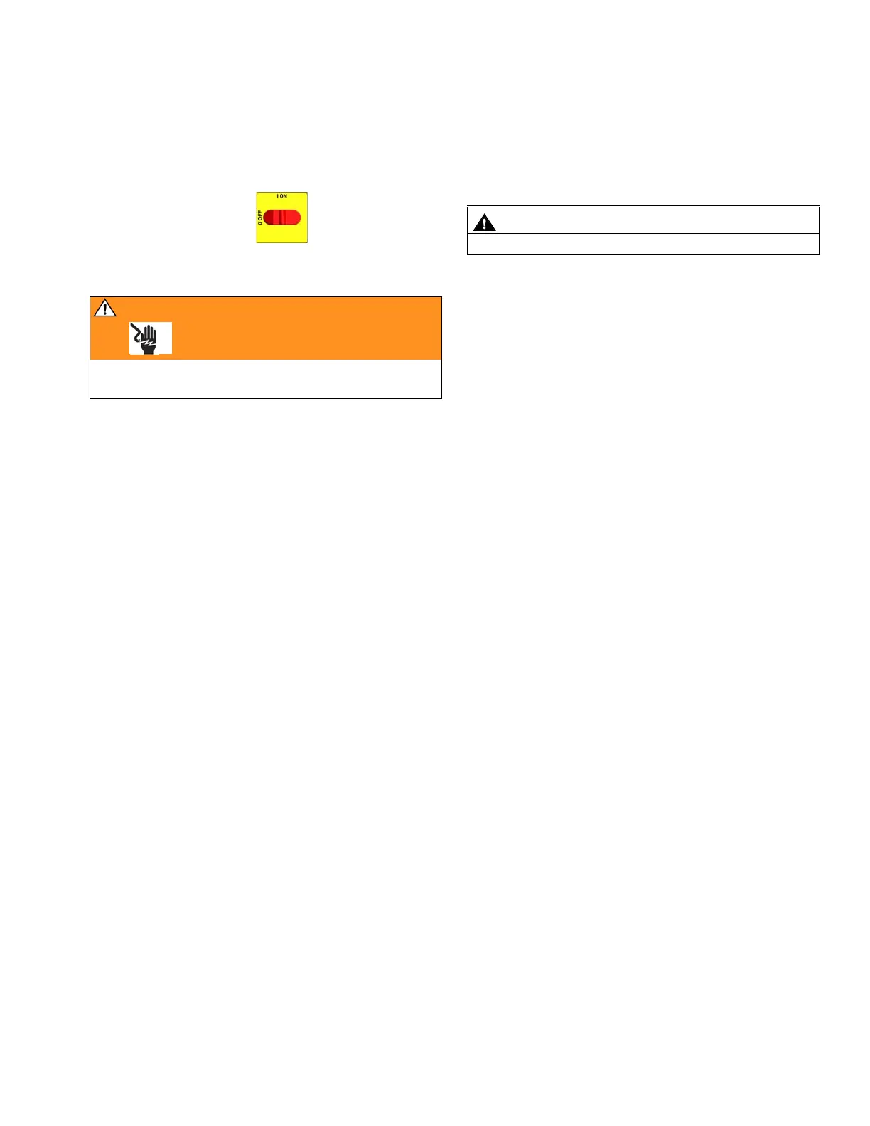
1. Turn main power OFF . Disconnect power
supply.
WARNING
Read warnings, page 6. Wait 5 min for stored voltage
to discharge (E-30 and E-XP2 models only).
CAUTION
Motor is heavy. Two people may be required to lift.

 Loading...