10
SECTION 3.SECTION 3.
SECTION 3.SECTION 3.
SECTION 3.
OPERAOPERA
OPERAOPERA
OPERA
TT
TT
T
OR CONTROLSOR CONTROLS
OR CONTROLSOR CONTROLS
OR CONTROLS
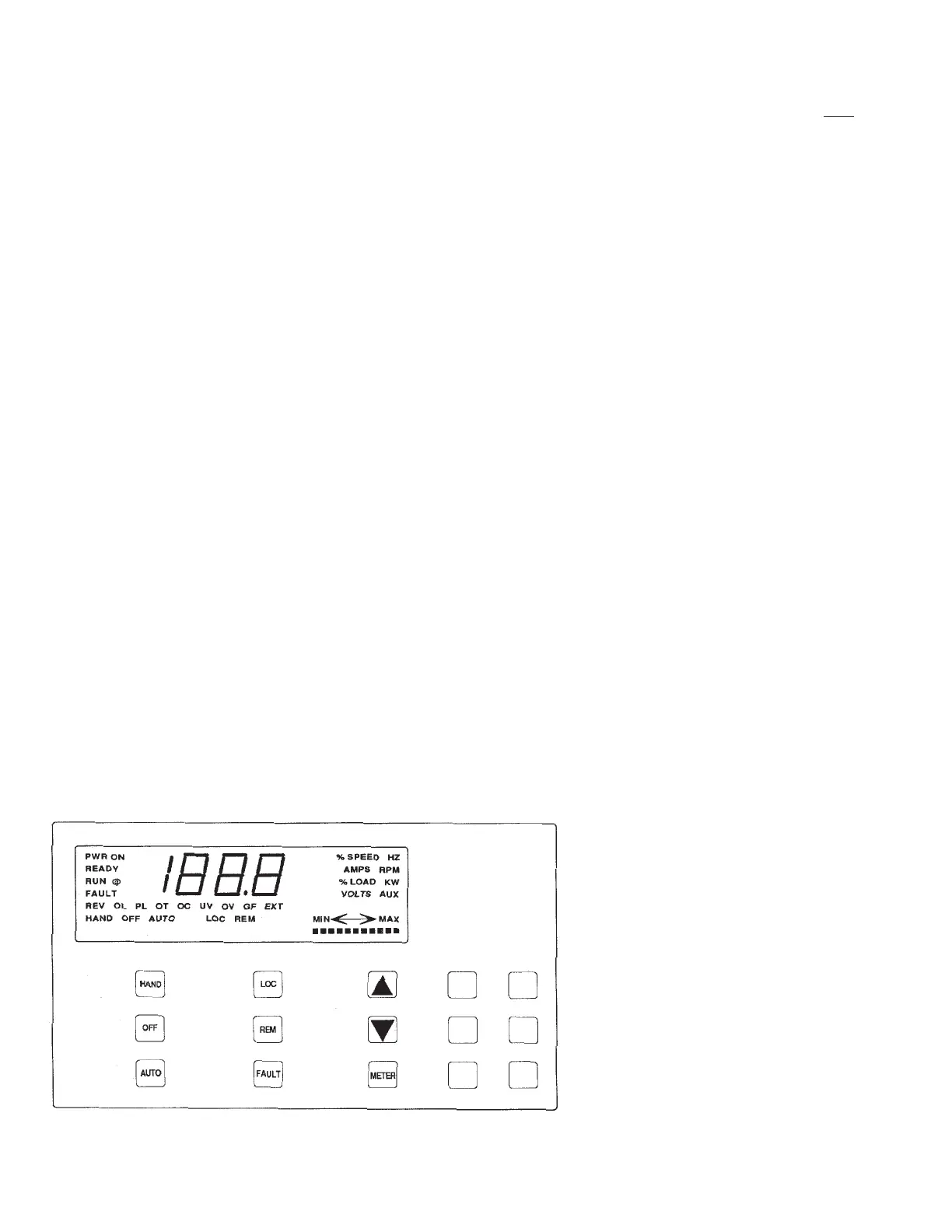
The following controls, displays and indicators are lo-
cated on the operator control panel on the door of the
1703 Series drives. This panel consists of soft touch
membrane switches, a 3½ digit backlit LCD display
and status indicating LCDs. On newer displays, the
back light will automatically turn itself off after a few
minutes of inactivity. To turn on the back light, press
any of the membrane switches.
3.1 SWITCHES3.1 SWITCHES
3.1 SWITCHES3.1 SWITCHES
3.1 SWITCHES
3.1.13.1.1
3.1.13.1.1
3.1.1
START SELECT SWITCHESSTART SELECT SWITCHES
START SELECT SWITCHESSTART SELECT SWITCHES
START SELECT SWITCHES
The start select switches consist of three mem-
brane switches (HAND, OFF, AUTO). The
start/stop functions of the drive are controlled
using these switches and the customer’s remote
start/stop contacts connected in series with ter-
minals 3 and 4 of terminal strip 4TB4.
HANDHAND
HANDHAND
HAND - The drive is commanded to energize
the run relay and start. In the HAND position
any customer interconnect contacts connected
to 4TB4 terminals 3 and 4 will be overridden.
The HAND LCD on the display panel will be
visible.
OFFOFF
OFFOFF
OFF - The drive is commanded to stop. In the
OFF position any customer interconnect con-
tacts connected to 4TB4 terminals 3 and 4 will
be overridden. The OFF LCD on the display
panel will be visible.
AUTOAUTO
AUTOAUTO
AUTO - The drive is commanded to start only if
the customer interlock contacts connected to
4TB4 terminals 3 and 4 are closed. The AUTO
LCD on the display panel will be displayed.
3.1.23.1.2
3.1.23.1.2
3.1.2
SPEED SELECT SWITCHESSPEED SELECT SWITCHES
SPEED SELECT SWITCHESSPEED SELECT SWITCHES
SPEED SELECT SWITCHES
The speed select switches consist of two mem-
brane switches (LOC, REM). These switches se-
lect the speed reference input to be tracked.
LOCLOC
LOCLOC
LOC - In the LOCAL position, drive speed is
controlled with the SPEED switches (▲, ▼) on
the operator panel. The LOC LCD on the dis-
play panel will be visible.
REMREM
REMREM
REM - The REMOTE selection commands the
drive to track the speed commands being pro-
vided from the customer’s control system on
4TB4 terminals 13 and 14. This input can be a
voltage or current signal. In the REMOTE
mode, the REM LCD on the display panel will
be visible.
3.1.33.1.3
3.1.33.1.3
3.1.3
SPEED SWITCHESSPEED SWITCHES
SPEED SWITCHESSPEED SWITCHES
SPEED SWITCHES
The speed switches consist of two membrane
switches (▲,▼) which are used to increase and
decrease the drive speed command when the
LOCAL mode is selected. The LOC LCD must
be displayed for the switches to control drive
speed. As the speed command is changed using
the up or down buttons, the “MIN <—> MAX”
display will light more or fewer LCD segments.
▲ - Increase speed command in
LOCAL mode
▼ - Decrease speed command in
LOCAL mode
3.1.4 METER SELECT3.1.4 METER SELECT
3.1.4 METER SELECT3.1.4 METER SELECT
3.1.4 METER SELECT
SWITCH SWITCH
SWITCH SWITCH
SWITCH
The meter select membrane switch is
used to step through the LCD display
meter functions. As the different meter
functions are selected, their signals will
be displayed on the 3½ digit LCD display
and the meter function selected will dis-
play that specific LCD section. The meter
function LCDs will only remain displayed
if that meter function has been installed.
The meter display sequence is:
% SPEED
% LOAD
Operator Control Panel and ReadoutsOperator Control Panel and Readouts
Operator Control Panel and ReadoutsOperator Control Panel and Readouts
Operator Control Panel and Readouts
 Loading...