28
Flue System and
Air Supply
9.5 General Guidance
All flue components are stainless steel
and fully insulated with 'O' ring seals
and locking bands.
The flue must terminate in a down
draught free area, i.e. at least 600mm
above the eaves or point of exit
through the roof, or preferably above
the ridge level.
The condensate may be allowed
to run back into the boiler. A
condensate drain at the base of the flue
system is not required.
The flue terminal must be at least
600mm from any opening into the
building, and 600mm above any
vertical structure or wall less than a
horizontal distance of 750mm from
the terminal.
No part of any flue system should be
made of an asbestos material;
aluminium must not be used in any part
of the flue. Only stainless steel flue
components should be used.
If the draught conditions are
satisfactory, the flue should terminate
with a standard cowl.
Refer to the locally applicable Building
Regulations, BS 5410:1 and OFTEC
Installation Requirements (OFTEC
Technical Book 4) for further guidance
on conventional flue systems.
9.4 Grant Horizontal System
This option uses the Grant Straight
Starter boiler connector, replacing the
low level terminal and flue guard
supplied with the boiler, along with
components from the Grant Green
system. See Figure 9-4.
A complete list of Grant Green system
flue components are given on page 29.
9.6 Air Supply
A permanent air supply must be
provided to the burner, sufficient to
ensure proper combustion of fuel and
effective discharge of combustion
products to the open air.
The ventilation openings provided in the
upper part of the front door of the boiler
casing must not be obstructed at any
time.
9 Flue System and Air Supply
Outdoor
Combi
Garden wall
Garden wall
Plan view showing
flue option through
adjacent garden walls
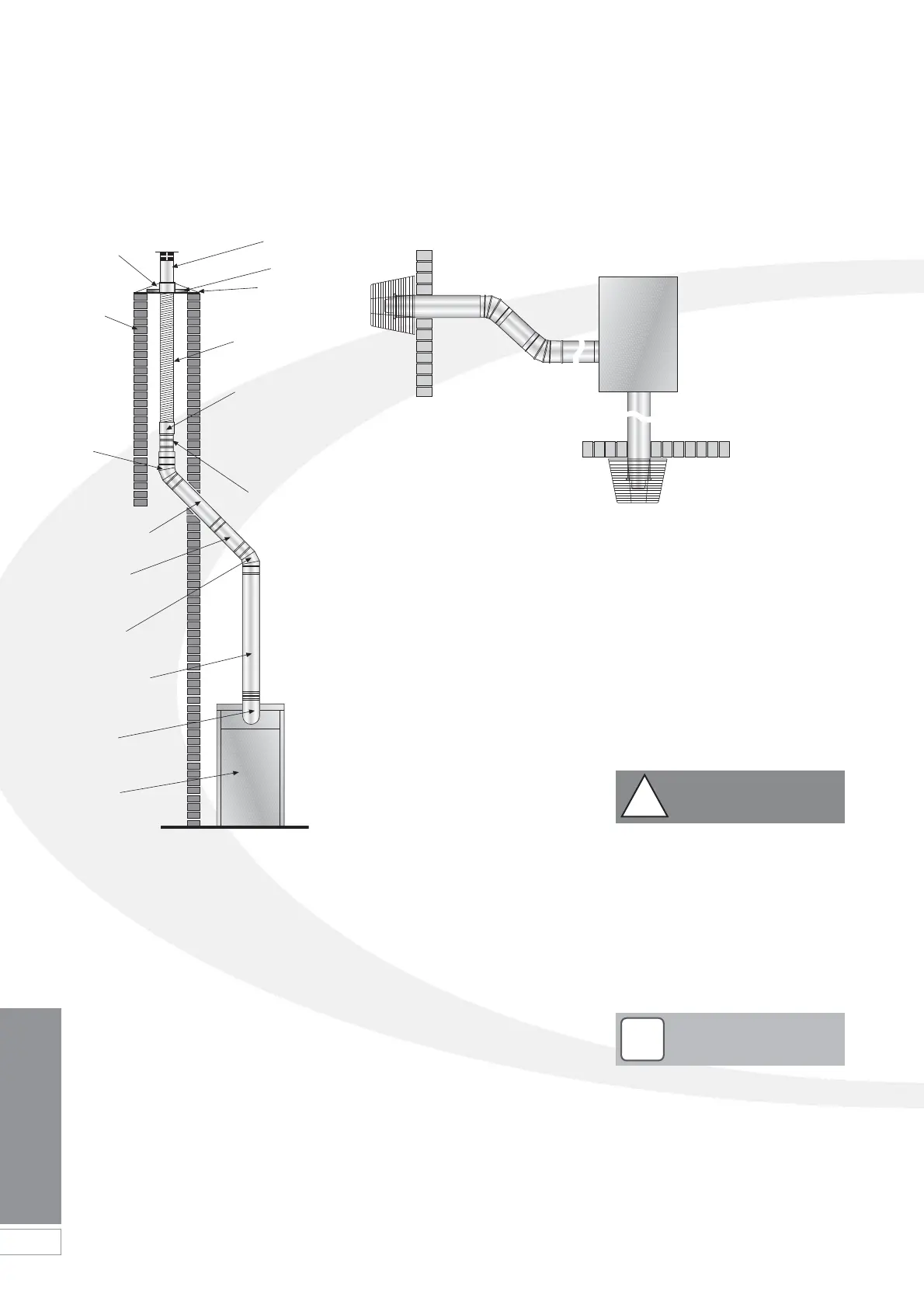
Figure 9-4: Outdoor horizontal flue system (Green system)
It is important to ensure that the flue
system is sealed and that
condensate cannot escape. Up to
1.5 l/h of condensate can be
produced in a conventional flue
system.
Do not use fire cement. The use of
high temperature silicone sealants is
recommended.
!
CAUTION
Figure 9-3: Vertical hybrid flue (Green
to Orange system)
Flaunching
Brick
chimney
45˚ Elbow
(Green
system)
Terminal
Clamp
Top plate
Twin-wall to
single-wall
adaptor
Flue extension
(Green system)
Adjustable
extension
(Green system)
45˚ Elbow
(Green system)
Flue extension
(Green system)
Outdoor
module
starter elbow
Outdoor
module
Flexible stainless
steel liner.
Note: The flue
liner is directional.
See Note page 27
Rigid to flexible
flue connector
(supplied in
Orange system kit).
Note: This
component must be
installed vertically
To comply with the requirements of
the Building Regulations Approved
Document J - conventional flue
systems must have a flue data plate.
A suitable data plate is supplied with
the current orange flue system and
should be displayed next to the
boiler or flue.
!
NOTE
 Loading...


