Commissioning
31
10.3 Running the Boiler
1. Relight the boiler and allow it to run
for at least 20 minutes.
2. Check the smoke number, if
satisfactory check the CO
2
. Set the
CO
2
to the value given in Section
2.3 for the boiler concerned.
Final combustion readings can only
be measured outside through the low
level flue terminal (or the test point
on the conventional flue starter
elbow when used) with all the casing
panels fitted.
3. Use the hexagonal key supplied to
adjust the burner air damper (see
Figure 10-3) as required. Turning the
screw anti-clockwise closes the
damper and increases CO
2
level,
turning the screw clockwise opens
the damper and reduces CO
2
level.
4. Re-check the smoke number if the
damper has been moved. Under no
circumstances must the smoke
number be above 1.
It is important that the air damper is
correctly set.
5. Check the flue gas temperature by
placing the combustion analyser in
the low level flue terminal (or into the
test point on the starter elbow if
either the Green system or Hybrid
system is used).
!
NOTE
10.4 Balancing the System
1. When the boiler has been adjusted
and is running satisfactorily, balance
the central heating system by
adjusting the radiator lock shield
valves. Start with the radiator
nearest the boiler and adjust the
valves to achieve the required
temperature drop across each
radiator. If thermostatic radiator
valves have been installed, check
the system bypass.
2. Switch off the boiler.
10.5 Completion
1. With the system hot, check again
for leaks, rectifying where necessary.
Drain the system while it is hot to
complete the flushing process. Refill
and vent the sealed system.
2. A suitable central heating system
inhibitor must be added to protect
the system against the effect of
corrosion.
3. A suitable antifreeze should be used
to prevent damage to the boiler in
areas where electrical power failure
can occur in winter months.
4. Replace the top, front and rear
panels as necessary.
After commissioning the boiler
complete the Commissioning Report
in the front of this manual and the
OFTEC CD/11 commissioning report.
Leave the top copy with the User and
retain the carbon copy.
If the boiler is to be left in service with
the User, set the controls and room
thermostat (if fitted) to the User's
requirements.
If the boiler is not to be handed over
immediately, close the boiler fuel supply
valve and switch off the electricity supply.
If there is any possibility of the boiler
being left during frost conditions,
then the boiler and system should be
drained. Alternatively, a suitable
antifreeze should be used.
To allow the boiler to be commissioned
and serviced correctly a combustion
test point is provided on the front
cleaning door.
The CO
2
and smoke test may all be
carried out using this test point.
The test point is not suitable for
measuring boiler efficiency or
conventional flue draught.
When using the test point on the
cleaning cover note that the flue gas
temperature reading will be higher than
that measured in the flue thus resulting
in an inaccurate efficiency reading.
To obtain an accurate flue gas
temperature and efficiency, the reading
can only be measured outside through
the low level flue terminal ( or the test
point on the conventional flue starter
elbow when used) with all the casing
panels fitted.
!
NOTE
!
NOTE
!
NOTE
!
CAUTION
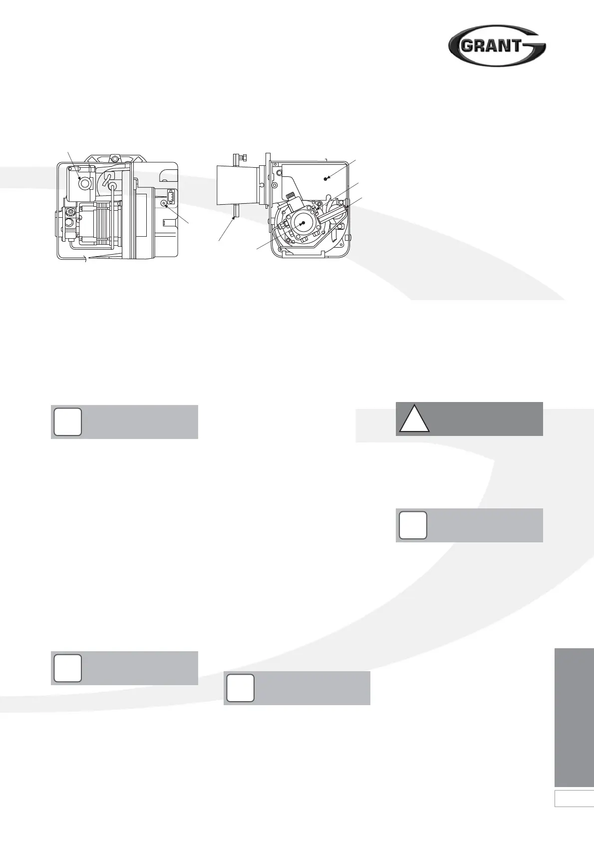
1. Pump
2. Control box
3. Reset button with lockout lamp
4. Flange with gasket
5. Air damper adjustment screw
6. Air supply tube connection
(balanced flue)
7. Pump pressure adjustment screw
8. Pressure gauge connection
Figure 10-3: RDB burner components
1
5
4
2
7
8
1
 Loading...


