8
Oil Storage &
Supply System
3 Oil Storage & Supply System
Single Pipe System
Where the storage tank outlet is above
the burner the single pipe system
should be used. The height of the tank
above the burner limits the length of
pipe run from the tank to the burner.
As supplied the burner is suitable for a
single pipe system.
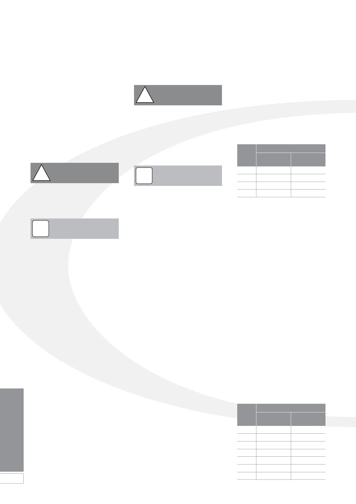
Head A Max Pipe Run (m)
(m) 10mm 12mm
OD Pipe OD Pipe
0.5 10 20
1.0 20 40
1.5 40 80
2.0 60 100
Head A Max Pipe Run (m)
(m) 10mm 12mm
OD Pipe OD Pipe
0 35 100
0.5 30 100
1.0 25 100
1.5 20 90
2.0 15 70
3.0 8 30
3.5 6 20
Two Pipe System
With the storage tank outlet below the
burner, a two pipe system should be
used. The pipe runs should be as
shown in Figure 3-2. The return pipe
should be at the same level in the tank
as the supply pipe, both being 75 to
100mm above the base of the tank.
The pipe ends should be a sufficient
distance apart so as to prevent any
sediment disturbed by the return
entering the supply pipe.
Avoid the bottom of the tank being
more than 3.5m below the burner.
A non-return valve should be fitted in
the supply pipe together with the filter
and fire valve. A non-return valve should
be fitted in the return pipe if the top of
the tank is above the burner.
The pump vacuum should not exceed
0.4 bar. Beyond this limit gas is released
from the oil.
For guidance on installation of top
outlet fuel tanks and suction oil
supply sizing, see OFTEC technical
book 3.
Available at www.oftec.org.uk
3.1 Fuel Supply
Fuel Storage
The tank should be positioned in
accordance with the recommendations
given in BS 5410:1:1997, which gives
details of filling, maintenance and
protection from fire.
A steel tank may be used and must be
constructed to BS 799:5:1987 and
OFS T200.
A galvanised tank must NOT be
used.
A plastic tank may be used and must
comply with OFS T100.
Plastic tanks should be adequately
and uniformly supported on a
smooth level surface, across their
entire load bearing base area, that is,
the area in contact with the ground.
Fuel Pipes
Fuel supply pipes should be of copper
tubing with an external diameter of at
least 10mm.
Galvanised pipe must not be used.
All pipe connections should preferably
use flared fittings. Soldered connections
must not be used on oil pipes.
Flexible pipes must not be used
outside the boiler case.
A remote sensing fire valve must be
installed in the fuel supply line at least
one metre before it enters the boiler
casing, with the sensing head located
above the burner.
Recommendations are given in
BS 5410:1:1997.
A metal bowl type filter with a
replaceable micronic filter must be fitted
in the fuel supply line adjacent to the
boiler. A shut-off valve should be fitted
before the filter, to allow the filter to be
serviced.
A flexible fuel line, adaptor and
1
/4" BSP
isolation valve is supplied loose with the
boiler for the final connection to the
burner. If a two pipe system or Tiger
Loop system is used, an additional
flexible fuel line (900mm) and
3
/8" to
1
/4"
BSP male adaptor are available from
Grant Engineering (UK) Limited (Part No.
RBS36).
Metal braided flexible hoses should be
replaced annually when the boiler is
serviced. Long life flexible hoses should
be inspected annually and replaced at
least every 60 months.
!
NOTE
!
CAUTION
!
CAUTION
Grant UK recommend that a fire valve
with a temperature rating of 95°C be
installed on any Grant Vortex Pro
Combi.
!
NOTE
 Loading...


