17
CONTROL
6 WIRED CONTROLLER OPERATION (OPTIONAL)
1 LCD Display
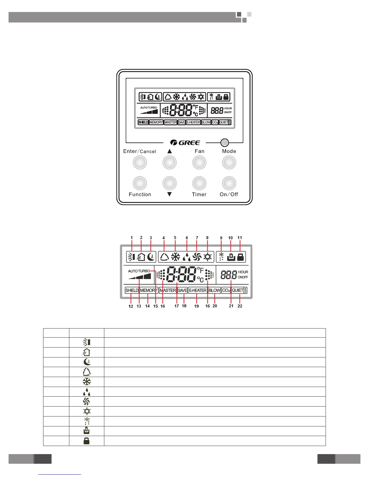
1.1 Symbols on the LCD
Fig.1 Appearance of the Wired Controller
1.2 Introduction to the Symbols on the LCD
Fig.2 Symbols on the LCD
Table 1 Introduction to the Symbols on the LCD
No. Symbol Function Description
1 It indicates the swing function.
2 It indicates the function of air exchange. (It is unavailable for this wired controller.)
3 It indicates the sleeping status.
4 It indicates each running mode of the indoor unit (AUTO mode). (It is unavailable for this wired controller. )
5 It indicates the “Cool” mode.
6 It indicates the “Dry” mode.
7 It indicates the “Fan” mode.
8 It indicates the “Heat” mode.
9 It indicates the defrosting mode. (It is unavailable for this wired controller.)
10 It indicates the gate control status.
11 It indicates the locking status.
 Loading...