GREE Photovoltaic Direct-driven Inverter Multi VRF Units
284
3.3 Disassembly and Assembly Procedure of Outdoor Unit Main
Parts
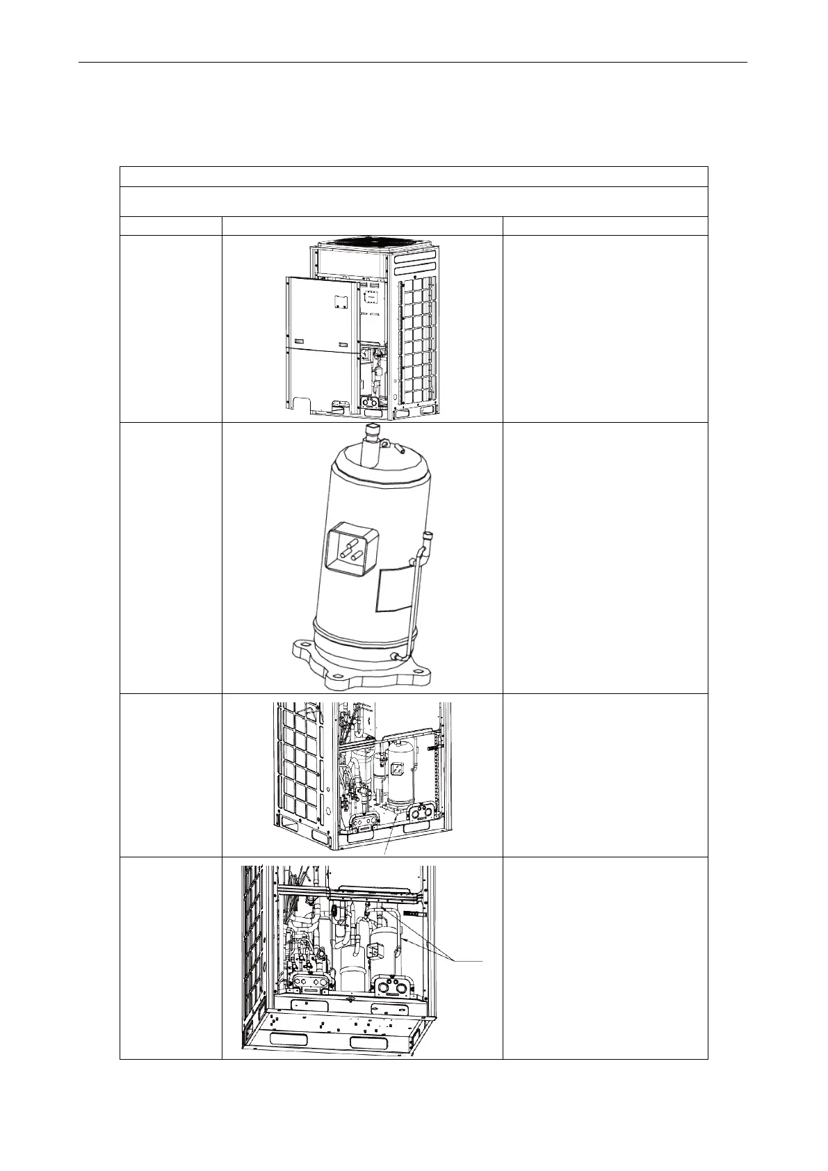
3.3.1 Disassembly and Assembly of Compressor
Removal procedure of compressor
Note: Before removing the compressor, make sure no refrigerant is inside the pipeline and power has
been disconnected.
Step Diagram Operation Procedure
.
front panels.
●Use a screwdriver to unscrew
the upper and lower front panels;
●Lift the front panel in order to
take them out. Note: Both the
upper panel and lower panel are
respectively to connect to the side
panels.
.
the power cord
and remove the
electric heating
belt, top
temperature
discharge
temperature
sensor.
●Remove the sound-proof sponge
from the compressor;
●
Use a screwdriver to unscrew
the power cord;
●Remove the power cord;
●Remove the electric heating belt,
top temperature sensor, and
discharge temperature sensor.
Note: Before removing the power
cord, mark the wiring terminals
corresponding to the colors of
power cord.
nuts of
compressor.
●Use a wrench to unscrew the 4
nuts of compressor.
.
suction and
discharge
pipes.
●Heat the suction and discharge
pipes by acetylene welding and
then remove the pipes;
●
During welding, charge nitrogen
into the pipes. The pressure
should be cont
0.5±0.1kgf/cm
2
(relative
pressure);
●Avoid nearby materials from
being burnt during welding.
 Loading...

