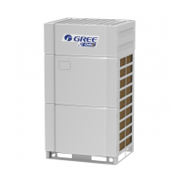
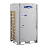
GREE Photovoltaic Direct-driven Inverter Multi VRF Units
260
Power
Run
D1 D2 D3 D4 D5 D6 D7 D8
Power Running
IDU and ODU
communication
Main
system
Main-
system
Reserved
ODU
→
IDU
ODU
→
IDU
Inter-system
communication
System1
→
System2
System1
→
System2
If the LEDs flash, the ODU and IDUs normally communicate; if the LEDs are steadily on,
communication is faulty. Check communication lines connecting the ODU and IDUs.
Note: After AP1 is replaced, you should power on the ODU and IDUs at the same time or power on
the ODU first; otherwise, “CC does not have module” will be prompted and a “C0 fault” alarm will be
reported by the IDUs.
③
Master ODU engineering debug setting
Debug the entire system after master module AP1 replacement.
④
System parameter setting
After debugging the system, reset system parameters identifical to the original system parameters.
For details, please refer to the section “Outdoor Unit Function Setting”.
3.1.3 Cautions on Replacement of Slave ODU AP1
Before replacing slave module AP1, set DIP identical to that of the faulty AP1, check wiring, and
then power on the AP1.
3.2 Method and Notice for Replacement of Compressor
3.2.1 Compressor Malfunction Diagnosis
3.2.1.1Unit can start normally
Step 1:
If units can start running normally, start up the unit so as to measure line current of the faulty
compressor. Use a pressure gauge to measure pressure of big and small valves and connect the gauge
to a PC in order to view the test data. Verify the current data against the current recommended in the
figures below. For inverter compressors, current will be deviated by 10% as the rotation speed and
operating condition vary.
E656DHD-65D2YG、E706DHD-72D2YG:
For inverter compressors E656DHD-65D2YG and E706DHD-72D2YG:
The figure below shows current curves that change with evaporating temperature and condensing
temperature while compressor works at 30Hz.
 Loading...


