GREE Photovoltaic Direct-driven Inverter Multi VRF Units
48
Rated capacity of indoor unit
C(Btu/h)
Pipe between indoor branch and IDU
48500<C≤72000 Φ19.05(3/4) Φ9.52(3/8)
72000<C Φ22.2(7/8) Φ9.52(3/8)
6 PIPE INSTALLATION AND INSULATION
6.1 Pipe Installation for the Cooling System
6.1.1 Precautions on Pipe Direction Design
Refrigerant pipe layout must be designed in accordance with the following principles:
(1) The air conditioning installation should not damage the bearing structure or the decorative style.
Air conditioning pipes should be laid out along the bottom of beam as possible. If pipes meet one
another at the same elevation, process based on the following principles:
1) Drain pipes enjoy the highest priority. Air ducts and pressure pipes should leave places for
gravity pipes.
2) Air ducts and small pipes should leave places for major pipes.
(2) The refrigerant pipe layout must be optimal in actual engineering with minimum pipe length and
bends. In this way, the performance of the unit can be maximized.
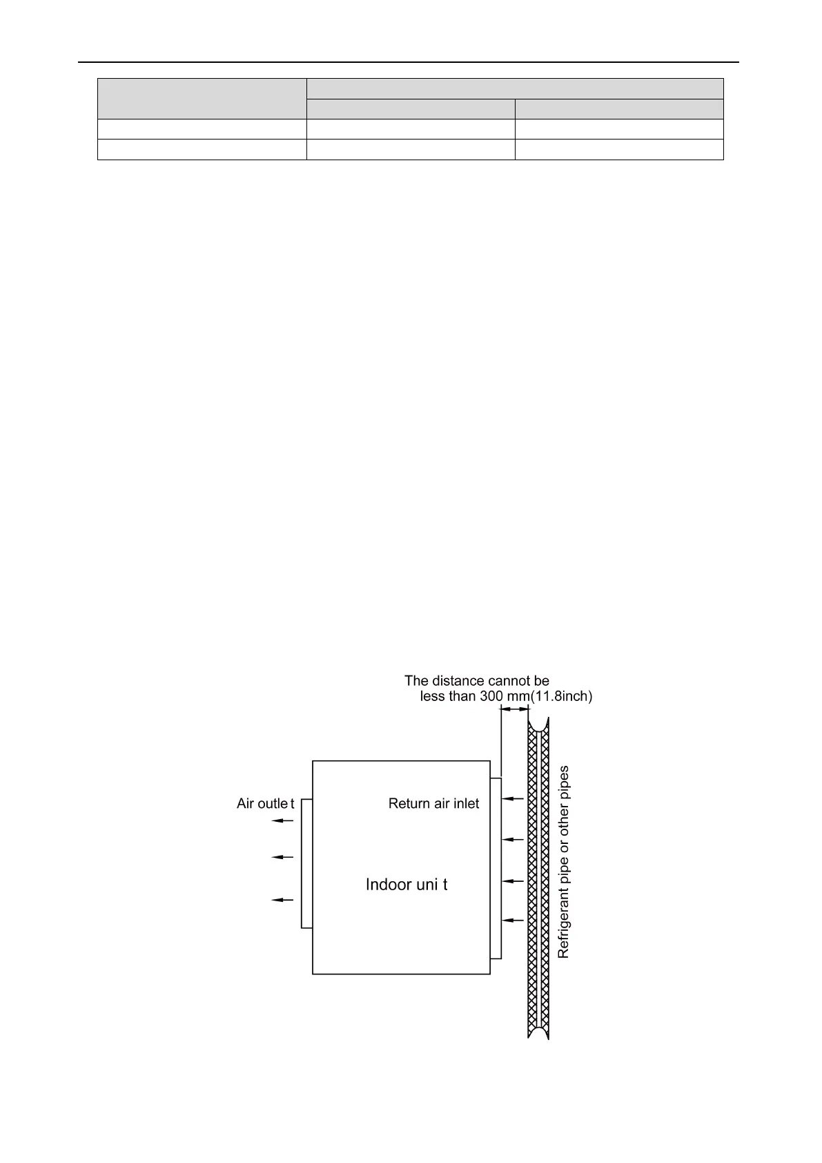
(3) The refrigerant pipe cannot affect air discharge and return of internal units. The minimum
distance between the refrigerant pipe with an insulation layer and the air return box is 300 mm
(11.8inch). If the air return or manhole is at the right lower part of the unit, the minimum distance
is 150 mm (5.9inch). When the refrigerant pipe needs to be laid at the air outlet side, avoid laying
the pipe at the front of the air outlet. The refrigerant pipe cannot connect to any part of the unit
except the joint points. If the preceding principles are not followed, performance of the unit will
be affected and running noises will be increased.
(4) The refrigerant pipe must be laid away from the manhole of the unit so that sufficient space can