Wired Controller XK49
10
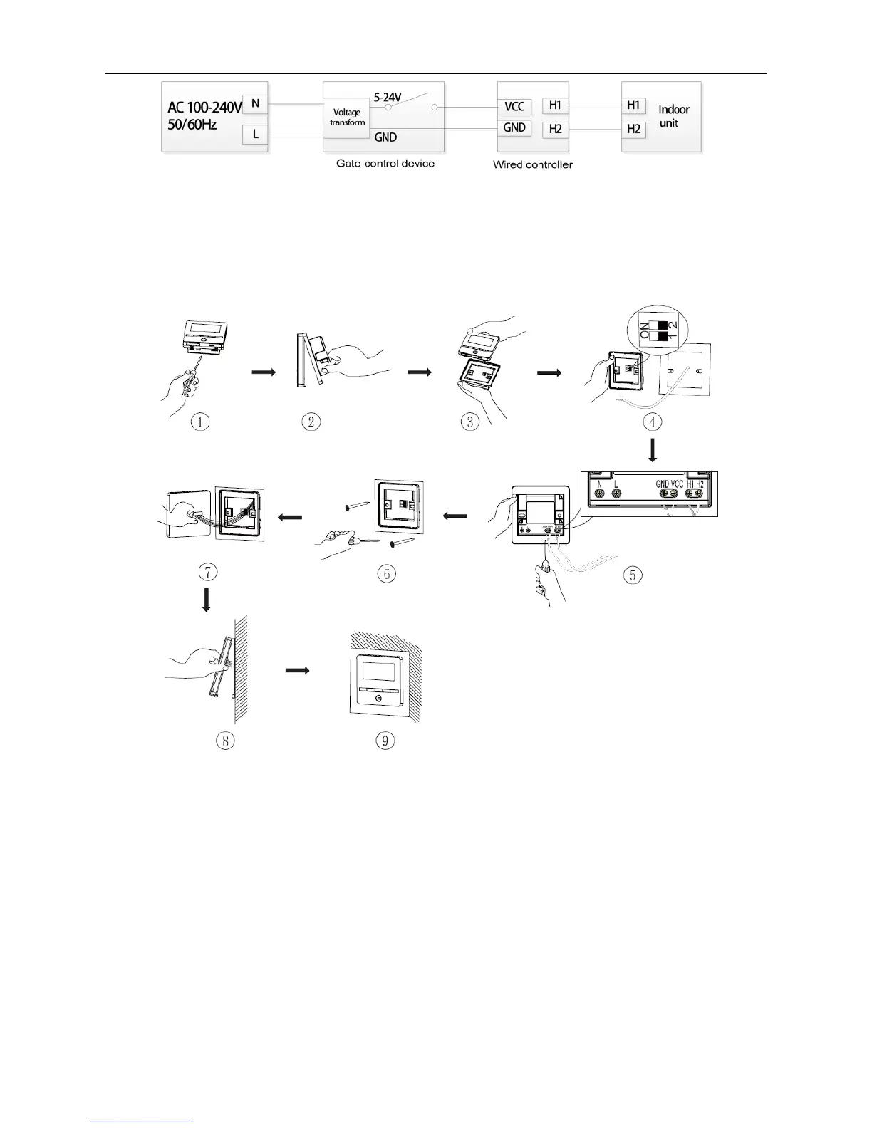
Figure 3.13 Wired Controller Connecting to Gate Control DC5-24V
Note: Users shall prepare the gate-control device by themselves.
3.1.4 Installation
Fig. 3.14 Installation diagram for wired controller
Fig. 3.14 is the simple installation process of wired controller; please pay attention
to the following items:
(1) Before installation, please cut off the power for indoor unit.
(2) Pull out the 2-core twisted pair line connected with the indoor unit from the
mounting hole and separately fix the twisted pair on the H1 and H2 terminal by screws.
(3) Gate-control wiring notice:
1) If the gate-control system is not involved, turn the No.1 switch of the DIP switch
S1 to the number side which is located at the bottom of the wired controller.
2) If the gate-control system is connected, make sure the No.1 switch of the DIP
 Loading...