EasyManua.ls Logo

Gree XK49 User Manual

Gree XK49
27 pages
To Next Page IconTo Next Page
To Previous Page IconTo Previous Page
Page #5 background imageLoading...
Page #5 background image
Wired Controller XK49
2
1.2 LCD Display Instruction
Table 1.1 LCD display instruction
No.
Symbols
Instructions
1
*
Auto mode (Under Auto mode, the indoor units will automatically select their
operating mode as per the temperature change so as to make the ambient
comfortable.)
2
Current set fan speed (including auto, low speed, medium-low speed, medium
speed, medium-high speed, high speed and turbo seven status)
3
Cooling mode
4
Dry mode
5
Fan mode
6
Heating mode
7
When inquiring or setting project number of indoor unit, it displays "NO." icon
8
Display "SET" icon under parameter setting interface
9
Up and down swing function
10
Display "CHECK" icon under parameter view interface
11
Gate-control function
12
Child Lock status
13
Outdoor unit defrosting status
14
Shielding status
15
It shows the setting temperature value(In case the wired controller is controlling a
Fresh Air Indoor Unit, then the temperature zone will display FAP)
16
One wired controller controls multiple indoor units
17
Memory status (The indoor unit resumes the original setting state after power
failure and then power recovery)
18
Current wired controller connects master indoor unit
19
The data display area will help to show the parameters checked or set.
20
It indicates the current wired controller is the slave wired controller
(address of wired controller is 02)
Question and Answer IconNeed help?

Do you have a question about the Gree XK49 and is the answer not in the manual?

Gree XK49 Specifications

General IconGeneral
BrandGree
ModelXK49
CategoryController
LanguageEnglish

Summary

1. DISPLAY

1.2 LCD Display Instruction

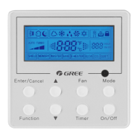
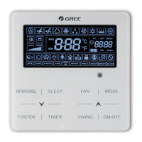
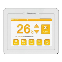
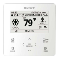
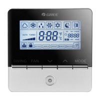
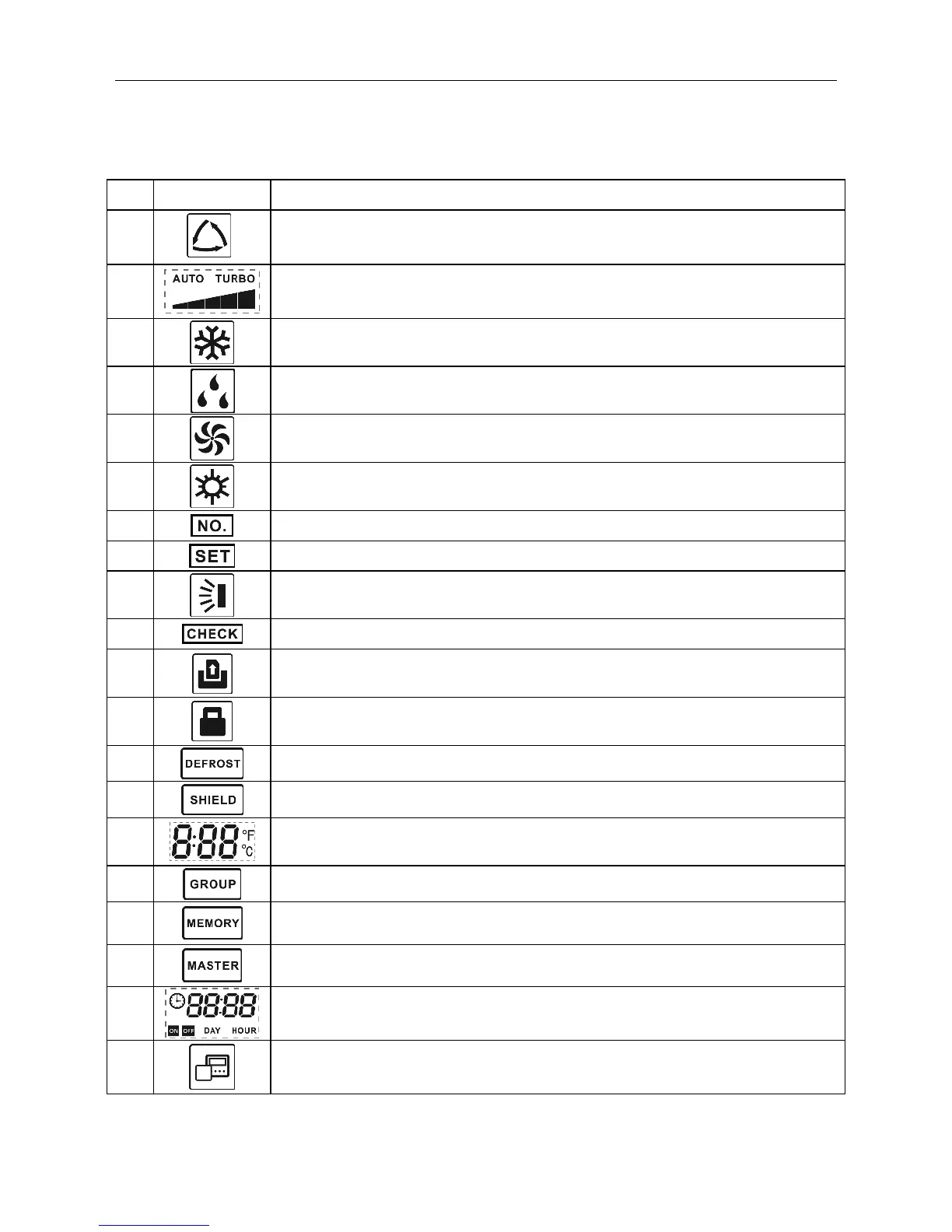
Provides a detailed explanation of each symbol and its meaning on the wired controller's LCD.

2. BUTTONS

2.2 Function Instruction of Buttons

Details the function of each button on the wired controller and their combined operations.

3. INSTALLATION AND COMMISSIONING

3.1 Installation of Wired Controller

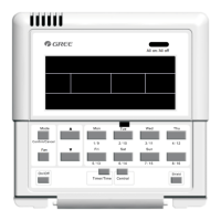
Covers the physical installation process and components of the wired controller.

3.1.1 Communication Line Selection

Explains how to select and wire the communication lines between indoor and outdoor units.

3.1.2 Installation requirements

Specifies the environmental and placement requirements for installing the wired controller.

3.1.3 Wiring Requirements

Details the wiring specifications for connecting the wired controller to indoor units.

3.1.4 Installation

Provides a step-by-step diagram and instructions for the physical installation of the wired controller.

3.2.3 Parameter Setting

Details how to access and modify various operational parameters of the wired controller.

4. OPERATION INSTRUCTIONS

5. ERROR DISPLAY

Related product manuals