CONNECT SERIES SERVICE MANUAL
16
ENGLISH
Troubleshooting
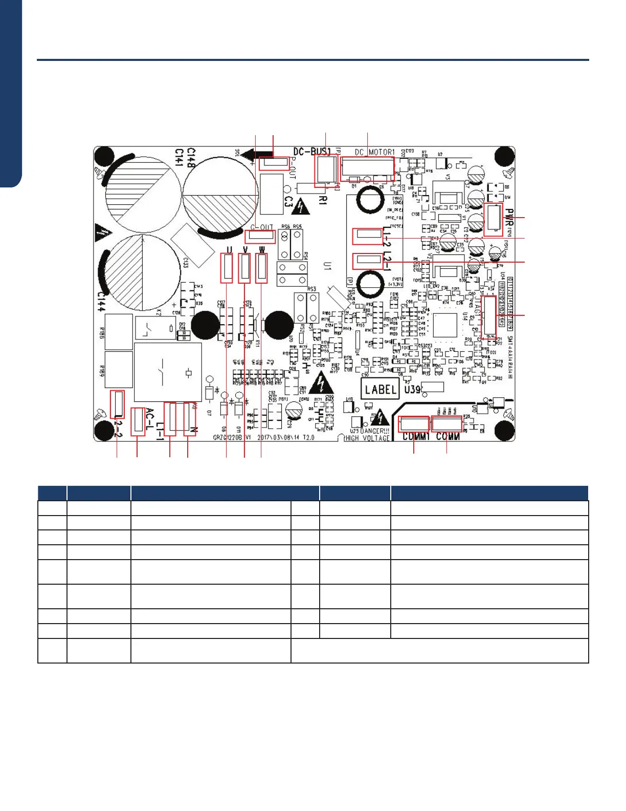
Drive Board
Model: AUH2436ZGDA
8
9
1
0
1
3
1
2
3
4
5
6
7
1
1
1
2
1
7
1
4
1
5
1
6
No. Printing Interface No. Printing Interface
1 L2-2 PFC induction wire (blue) 10 P-OUT Reserved
2 AC-L Live wire 11 L1-2 PFC induction wire (white)
3 L1-1 PFC induction wire (brown) 12 L2-1 PFC induction wire (yellow)
4 N Neutral wire 13 G-OUT Reserved
5 COMM1
Communication terminal, same with
COMM
14 U Compressor U phase terminal
6 COMM
Communication terminal, same with
COMM1
15 V Compressor V phase terminal
7 PWR Drive power supply terminal 16 W Compressor W phase terminal
8 DC-MOTOR1 DC fan terminal 17 JTAG1 Programming interface (for testing)
9 DC-BUS1
Power discharge terminal (for
testing)
 Loading...