16 HARDI
®
NAVIGATOR 550M, 800M, 1000M CENTRIFUGAL OPERATOR'S MANUAL
3.5 Installation Of P.T.O. Shaft
(
P.T.O. Driven Pumps Only
)
WARNING:
THE P.T.O. SHAFT ANGLE WILL CHANGE WHEN RAISING
AND LOWERING THE AXLE SYSTEMS AND/OR CLEVIS. TO
PREVENT EXCESSIVE LOADING AND BINDING ON THE P.T.O.
SHAFT, IT MAY BE ADVISABLE TO LEAVE THE P.T.O. SHAFT
DISCONNECTED UNTIL THIS OPERATION IS COMPLETED.
THEN THE P.T.O. SHAFT ADJUSTMENTS CAN BE MADE.
Initial installation of the shaft is done as follows:
1. Attach sprayer to tractor and set sprayer in the position with shortest
distance between the tractor and sprayer pump P.T.O. shafts.
2. Stop engine and remove ignition key.
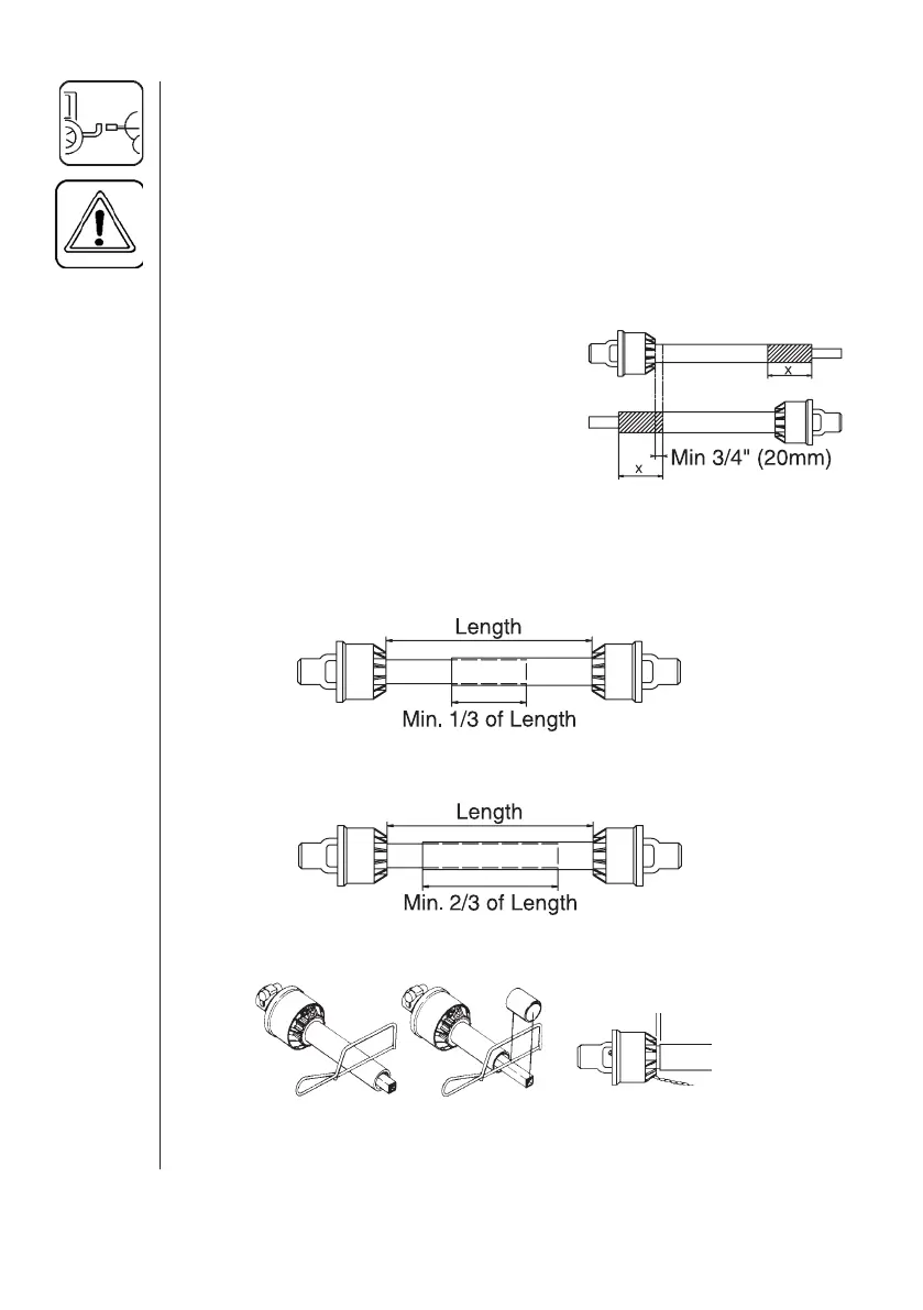
3. If P.T.O. shaft must be shortened, the
shaft is pulled apart. Fit the two shaft
parts at tractor and sprayer pump and
measure how much it is necessary to
shorten the shaft. Mark the protection
guards.
Note: The minimum allowable overlap for the shaft depends on the pump
model.
Pump with 6 splines (540 r.p.m.)
The shaft must always have a minimum overlap of 1/3 the length.
Pump with 21 splines (1000 r.p.m.)
The shaft must always have a minimum overlap of 2/3 the length.
4. The two parts are shortened equally. Use a saw, and fi le the profi les
afterwards to remove burrs (Fig. 8).
5. Grease the profi les, and assemble male and female parts again.
6. Fit the shaft to tractor and sprayer pump.
Fig. 6
Fig. 7
min. 3/4" (20mm)
Fig. 8
 Loading...