9
SECTION 3. INSTALLATION
Indoor installation and venting:
The following installation and service clearances must be
maintained from combustible materials.
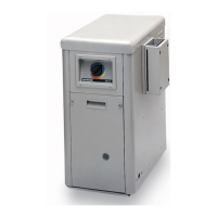
Do not Install In a closet!
Do not install an H210 indoor!
For alcove installations, the drafthood (DHI) shall be installed
so as to be in the same atmospheric pressure zone as the com-
bustion air inlet to the pool heater.
Air supply:
Indoor installations and outdoor shelters must be provided
with adequate combustion and ventilation air vents to assure
proper heater operation. These vents must be sized according
to the requirements stated in A. and B. below and must never be
obstructed when heater is in operation.
When air blowers are used in spa/hot tub installations, cau-
tion must be observed to insure sufcient combustion air is avail-
able to the gas heater for proper combustion. A separate blower
air duct is recommended.
Equipment located in conned spaces:
A. All Air Supply From Inside The Building: The conned
space shall be provided with two permanent openings com-
municating directly with an additional room(s) of sufcient
volume so that the combined volume of all spaces meets the
criteria for an unconned space (a space whose volume is
not less than 50 cubic feet per 1000 BTUH). The total input
of all gas utilization equipment installed in the combined
space shall be considered in making this determination. Each
opening shall have a minimum free area of 1 square inch per
1,000 BTU per hour of the total input rating of all gas utiliza-
tion equipment in the conned space, but not less than 100
square inches. See Figure 13. One opening shall be within
12 inches of the top and one within 12 inches of the bottom of
the enclosure.
B. All Air Supply From Outdoors: The conned space shall
be provided with two permanent openings, one commenc-
ing within 12 inches of the top and one commencing within
12 inches of the bottom of the enclosure. The openings shall
communicate directly, or by ducts, with the outdoors or spac-
es (crawl or attic) that freely communicate with the outdoors.
1. When directly communicating with the outdoors, each opening
shall have a minimum free area of 1 square inch per 4,000
BTU per hour of total input rating of all equipment in the enclo-
sure. See Figure 13.
2. When communicating with the outdoors through vertical ducts,
each opening shall have a minimum free area of 1 square
inch per 4,000 BTU per hour of total input rating of all equip-
ment in the enclosure. See Figure 13.
3. When communicating with the outdoors through horizontal
ducts, each opening shall have a minimum free area of 1
square inch per 2,000 BTU per hour of total input rating of all
equipment in the enclosure. See Figure 13.
4. When ducts are used, they shall be of the same cross-sec-
tional area as the free area of the openings to which they con-
nect. The minimum dimension of rectangular air ducts shall be
not less than 3 inches.
! NOTE: For more detailed methods of providing air for com-
bustion and ventilation, refer to latest edition of the National Fuel
Gas Code, ANSI Z223.1.
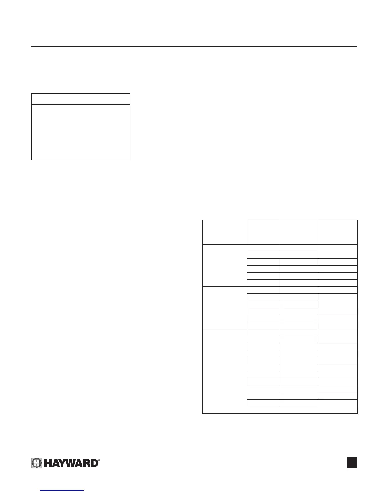
Figure 13
Figure 12
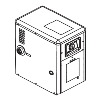
Indoor Installations*
Top - 36”
Non-combustible oor
Front - Unobstructed
Vent - 6”
Back - 6”
Right side (Water side) - 12”
Left side - 6”
*Canada outdoor shelters
Free Area per Btu
Requirement
Total Input
(btu/hr)
Combustion Air
Free Area
Required
(sq. in.)
Ventilation Air
Free Area
Required
(sq. in.)
1 sq. in. per
1,000 btu/hr
(paragraph A)
150,000 150 150
200,000 200 200
250,000 250 250
300,000 300 300
350,000 350 350
400,000 400 400
1 sq. in. per
2,000 btu/hr
(paragraph B-3)
150,000 75 75
200,000 100 100
250,000 125 125
300,000 150 150
350,000 175 175
400,000 200 200
1 sq. in. per
4,000 btu/hr
(paragraph B-1)
150,000 37.5 37.5
200,000 50 50
250,000 62.5 62.5
300,000 75 75
350,000 87.5 87.5
400,000 100 100
1 sq. in. per
250 btu/hr
(below-ground
installation)
150,000 600 600
200,000 800 800
250,000 1000 1000
300,000 1200 1200
350,000 1400 1400
400,000 1600 1600
 Loading...