13
SECTION 3. INSTALLATION
Plumbing connections:
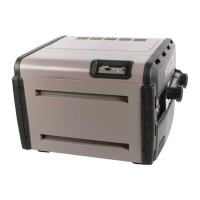
1. The H-Series heater is equipped with CPVC SCH-80
anged pipe nipples, union nuts, neoprene O-rings
for use with 2” pipe connections. Figure 22 shows the
method for installing these parts on the front header.
! NOTE: Assemble these parts to heater prior to plumb-
ing. Tighten union nuts securely before gluing ttings to
ends of pipe nipples.
2. The CPVC SCH-80 anged pipe nipples must be
installed on the heater inlet and outlet without modica-
tion. CPVC SCH-80 plastic has an ASTM rating of F441
and is NSF approved. The opposite ends of the pipe
nipples should be attached to the ltration system as
particular installation dictates.
3. Pipe, ttings, valves and any other element of the lter
system may be made of plastic materials, if acceptable
by the authority having jurisdiction. 1 1/2” plastic pipe if
used, will slide directly into the anged pipe ends.
4. Heat sinks (heat traps), reman switches and check
valves are not necessary on the H-Series heaters.
However, if there is any chance of “back-siphoning” of
hot water when the pump stops running, it is suggested
that a check valve be used on the heater inlet pipe.
5. The vari-o by-pass that is built into the front header
will maintain proper ow through the heat exchanger
if the ow rate is within the range for the heater. See
Figure 23.
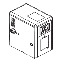
6. If the normal pump and lter system ow rate exceeds
125 gpm then a manual by-pass valve, as shown in
Figure 24, must be installed as follows: Install a ow
meter on the outlet line of the heater. Adjust the manual
by-pass valve until the ow rate is within the rates re-
quired for the heater. Once the valve is set, the position
should be noted and the valve handle removed to avoid
further adjustment.
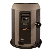
7. Figure 25 shows a typical pool piping diagram and lay-
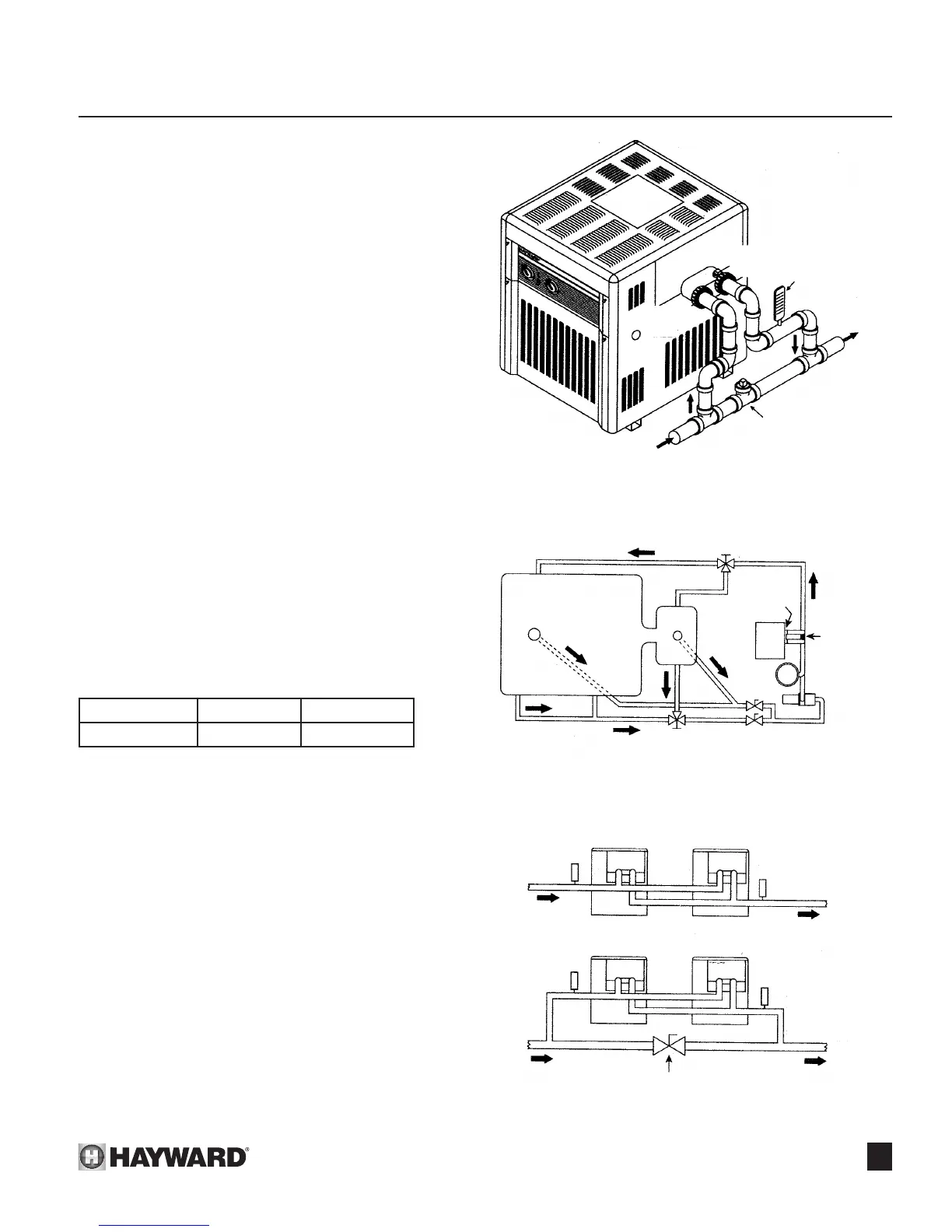
out for pool equipment. Figure 26 shows multiple heater
usage for very large pools with and without an external
by-pass (balancing) valve.
Figure 23
Figure 24: Manual By-pass Valve
Figure 25: Typical Plumbing To Pool
Figure 26: Multiple Heater Hookups
RECOMMENDED FLOW RATE IN GPM
Model Minimum Maximum
H150-H400 25 125
VALVE
FLOW METER
FROM PUMP
AND FILTER
CONNECTION
TO HEATER
OUTLET
RETURN TO
POOL/SPA
CONNECTION
TO HEATER
INTLET
3-WAY VALVE
TO POOL
HEATER
FILTER
PUMP
FROM
POOL
MAIN
DRAIN
3-WAY
VALVE
RELIEF
VALVE
OPTION
POOL
SPA
MANUAL
BY-PASS
VALVE
(if necessary)
BALANCING VALVES
FOR SKIMMER
AND DRAIN
THERMOMETER
THERMOMETER
THERMOMETER
ADJUST
BALANCING VALVE
TO OBTAIN A
20ºF DIFFERENTIAL
ACROSS
THERMOMETERS
THERMOMETER
BALANCING VALVE
TO POOL
TO POOL
FROM FILTER
FROM FILTER
2”
2”
2”
2”
 Loading...