14
SECTION 3. INSTALLATION
Installation above pool/spa surface:
If heater is installed less than three (3) feet above the surface
of the pool/spa water, install eyeball ttings or directional ow t-
tings on the end of the return water line to the pool/spa to create
adequate back pressure at the heater to operate the pressure
safety switch when lter pump is running.
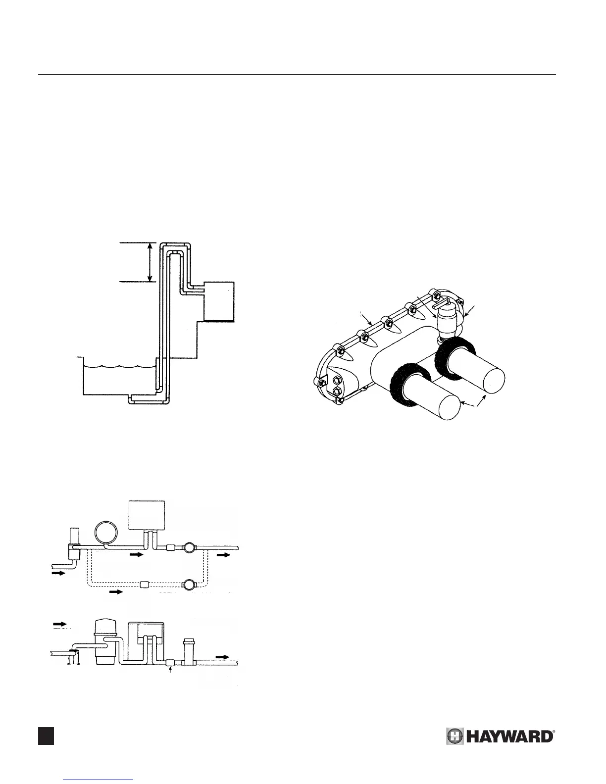
If heater is installed more than three (3) feet above surface of
pool/spa water, install a loop as shown on Figure 27 to prevent
drainage of water in heater during lter change.
For installation below pool/spa surface, refer to Section 4.
Automatic chlorinators and
chemical feeders:
If used, a chlorinator must be installed down stream from the
heater in the pool return line and at a lower elevation than the
heater outlet connection. See Figure 28. Install a separate posi-
tive seal, corrosion resistant check valve (EXAMPLE: Rainbow
Plastics #17288 or #172323) between the heater outlet and chlo-
rinator to prevent highly concentrated sanitizers from back-si-
phoning into the heater. Back-siphoning usually occurs when the
pump is shut off and a pressure-suction differential is created.
Pressure relief valve:
It may be necessary to install a pressure relief valve to con-
form with local building codes. A 3/4” pressure relief valve with
a discharge capacity greater than or equal to the BTUH input of
the heater and a pressure relief rating less than the heater work-
ing pressure is recommended (see rating plate).
A 3/4” NPT connection is provided in the front header for
installation of a pressure relief valve. See Figure 29. The valve
shall be installed directly to the header in a vertical position. To
avoid scalding or water damage due to relief valve operation,
connect a drain pipe to the valve outlet and run the line to a safe
place of discharge. The drain pipe must be at least the same
size as the valve discharge connection throughout its entire
length and must pitch downward from the valve. No shutoff valve
or restriction shall be installed between the relief valve and the
discharge of the drainline. The valve lever should be lifted at
least once a year to ensure that the waterway is clear.
Figure 27: Heater Installation Above Pool
HIGHER THAN
TOP OF HEATER
HEATER
WATER LEVEL
HEATER
CHLORINATOR
CHLORINATOR
CHECK VALVE
OPTIONAL (PREFERRED)
CHLORINATOR HOOKUP
PUMP
PUMP FILTER HEATER
FILTER
TOP VIEW
SIDEVIEW
FROM
POOL
RETURN
TO POOL
RETURN
TO POOL
FROM
POOL
CHECK
VALVE
CHECK
VALVE
Figure 28: Automatic Chlorinator
Figure 29: Pressure Relief Valve
FRONT HEADER
DISCHARGE
CONNECTION
PLUMBING
CONNECTIONS
PRESSURE RELIEF VALVE
 Loading...