31
Control Locations:
The following sections give a brief overview of the various
heater controls and service/replacement procedures. The text
describes the intended purpose of the controls. See Figure 50
for general location of the controls.
Electrical wiring:
! NOTE: If it is necessary to replace any of the original
wiring, it must be replaced with wiring suitable for 105°C {Style
1015 or 1230) or its equivalent.
System Switch:
A two-way “ON/OFF” rocker switch is provided for single ther-
mostat heaters and a three-way “POOL/OFF/SPA” rocker switch
is provided on dual thermostat heaters.
To replace system switch:
1. Turn pump and main gas valve off. Turn thermostat to
lowest setting.
2. Turn electricity off on electronic ignition heaters.
3. Open control panel and remove wires from system switch.
4. Press the ends of system switch in and remove from panel.
5. Replace system switch and reverse above procedure.
Temperature controls:
Millivolt Heaters
Millivolt heaters are manufactured with a mechanical thermo-
stat models. To replace thermostat:
1. Turn pump, main gas valve and system switch off.
2. Remove thermostat knob, open control panel and remove
right side access panels.
3. Remove the thermostat bulb from the front header.
! NOTE: Using needle nose pliers to pull out copper strip
makes bulb removal easier. Pull thermostat capillary tube and
bulb through the oval slot in the intermediate panel.
! CAUTION: Be careful not to crimp capillary tube as it could
break from mishandling.
4. Remove wires from thermostat.
5. Remove screws that secure thermostat mounting bracket to
control panel.
6. Replace thermostat and reverse above procedures.
Electronic Heaters
Electronic heaters are manufactured with an integrated
thermostat and ignition control that operates the heater. The
replacement part is available as an assembly only. To replace
control panel assembly:
1. Turn pump, main gas valve and electricity off.
2. Unplug wires from rear circuit board.
3. Remove four screws retaining the plastic bezel to the
sheet metal.
4. Pull entire assembly through the front panel.
5. Replace control panel assembly and reverse above
procedures.
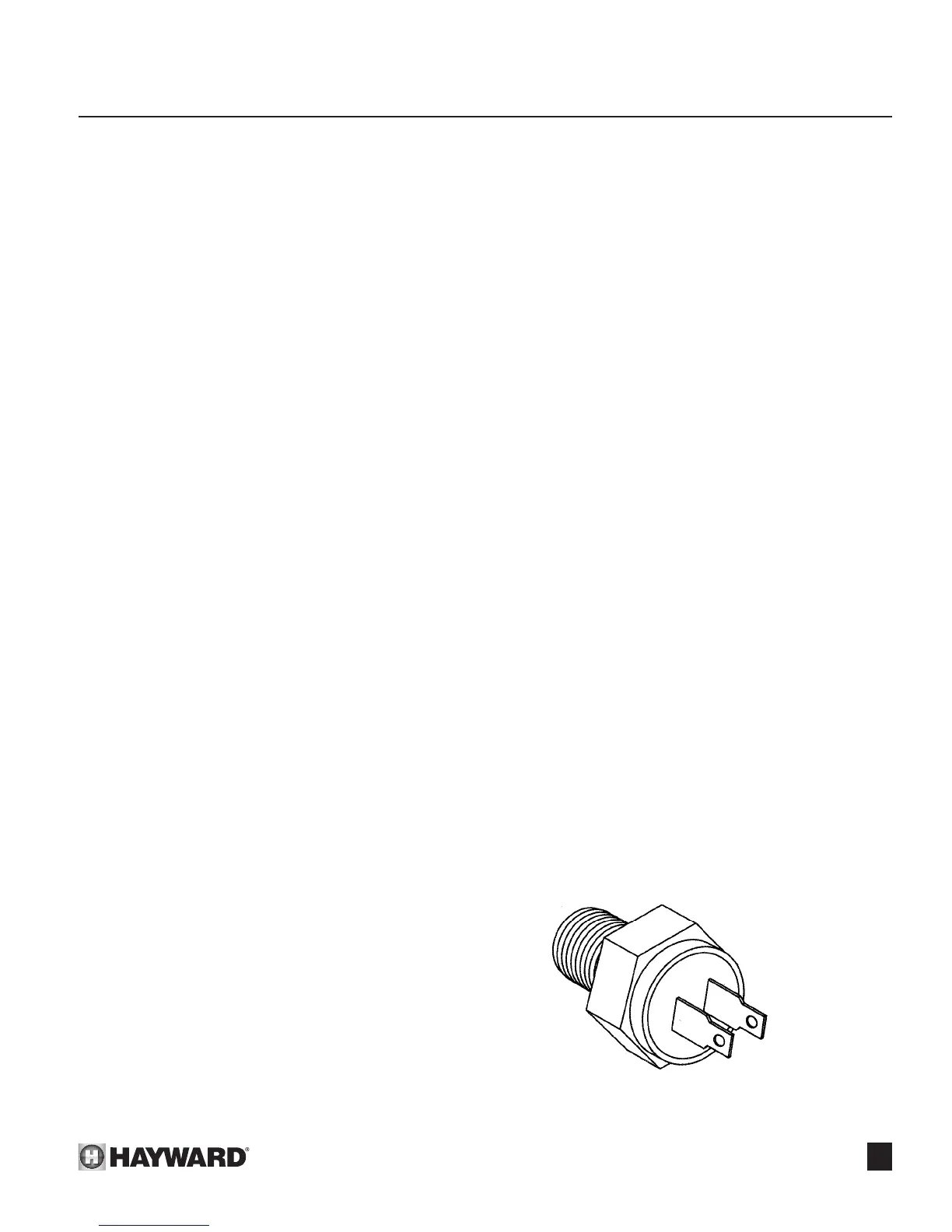
High limits:
The high limit is an automatically resetting safety device
wired in series with the thermostat, pressure switch, temperature
limiter switches, and main gas valve. See Figure 51. The pool
heater is equipped with two automatic high limits. The limits are
located on the front and rear headers
! CAUTION: The two limit switches have different tempera-
ture settings (check Parts List).
If the water temperature at the location of the limit should
exceed the limit set point, the main gas valve will shut off gas
supply to the burners.
An erratic high limit is often an indication of a problem with
water ow. Reduced ow may be caused by:
1. Clogged lter or strainer.
2. Excessive ow through the external bypass valve if one
is used.
3. Lime scale accumulation in the heat exchanger.
To replace high limits:
1. Turn pump, main gas valve and system switch off.
2. Turn electricity off on electronic ignition heater.
3. Drain heat exchanger of all water.
4. Remove side access panels.
5. Remove wires from high limits.
6. Unscrew the defective high limit.
7. Replace the high limit and reverse above procedures.
SECTION 6. QUALIFIED TECHNICIAN - MAINTENANCE/SERVICING
Figure 51: High Limit
 Loading...