30
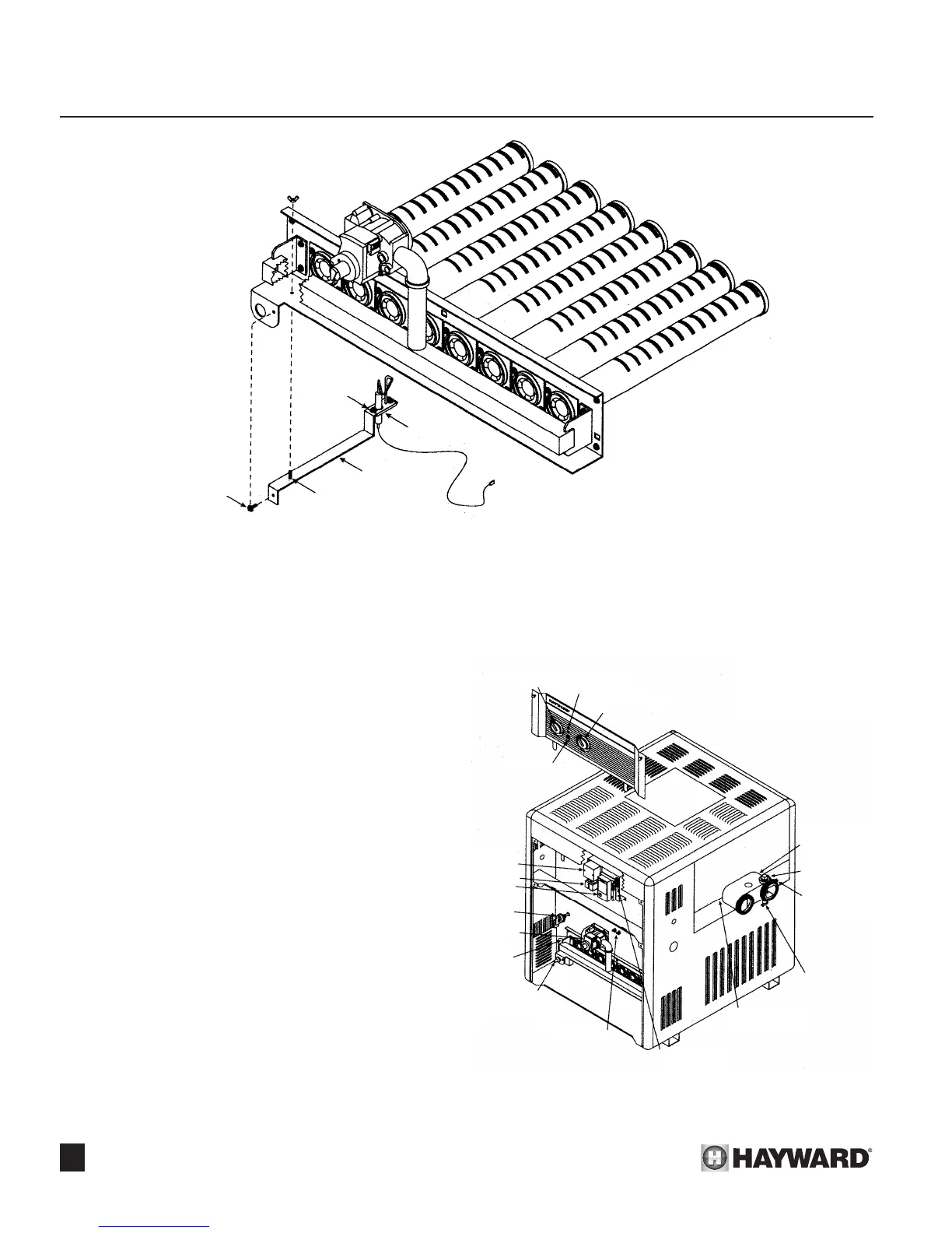
CLINCH STUD
IGNITOR
BRACKETS
SECURING SCREW
2 SCREWS
SHOWN WITHOUT SURROUNDING
HEATER CABINET FOR CLARITY
SECTION 6. QUALIFIED TECHNICIAN - MAINTENANCE/SERVICING
Ignitor assembly removal: (Electronic Ignition Heater Only) (See Figure 49.)
1. Disconnect the electrode/sensor wire from the ignition module.
2. Remove screw securing ignitor bracket to clear locating
stud and remove assembly from heater.
3. To service or replace ignitor remove two screws securing ig-
nitor to ignitor bracket and disconnect electrode ignitor wire.
4. Recheck spark gap (9/64”).
5. Reverse the above procedures for installation.
Main burner orices:
The main burner orices can be removed from the mani-
fold with a 7/16” wrench without having to remove the burner
assembly from the heater. After cleaning or replacing orices
re-install in manifold being careful not to overtighten as a leak
may result.
! CAUTION: Do not enlarge orice holes.
Gas conversion:
The factory installed gas train, where appropriate, may
be changed from natural gas to propane or from propane to
natural gas, using the appropriate conversion kit, available
from the factory. Gas conversions are to be performed only
by a qualied agency. Detailed instructions are included with
each kit.
! NOTE: Conversion kits are not available in Canada.
Conversions must be done by the conversion station at Hay-
ward Pool Products Canada, Inc.
Figure 49: Ignitor Assembly Removal
SPA THERMOSTAT
POOL THERMOSTAT
SYSTEM SWITCH
BY-PASS VALVE
(INSIDE FRONT
HEADER)
FLOW CONTROL
THERMOSTAT
(ON FRONT HEADER)
LED LIGHTS
DRAIN VALVE
HIGH LIMITS
(ON FRONT AND
REAR HEADER)
THERMOSTAT
BULB WELL(S)
ON FRONT HEADER
TERMINAL BLOCK
TEMPERATURE
LIMITER SWITCHERS
FIELD WIRING
JUNCTION BOX
TRANSFORMER
GAS VALVE
CONTROL
MODULE
PRESSURE
SWITCH
CLICKLITE
TM
(MILLIVOLT
UNITS ONLY)
PILOT
ASSEMBLY
(ON LEFT SIDE
OF BURNER
ASSEMBLY)
Figure 50: Control Locations
 Loading...