User Manual of Network Video Recorder
27
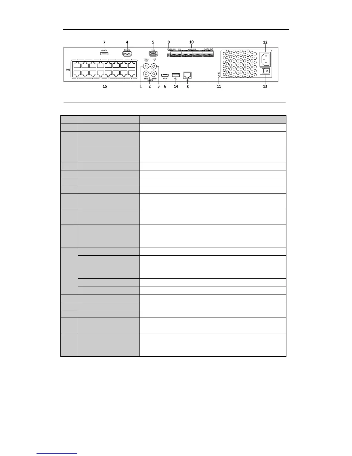
Figure 1. 13 DS-7716 / 7732NI-SP
Table 1. 7 Description of Rear Panel Interfaces
BNC connector for video output.
BNC connector for audio output. This connector is synchronized with
CVBS video output.
BNC connector for audio output. This connector is synchronized with
VGA video output.
BNC connector for audio input.
Connector for RS-232 devices.
DB9 connector for VGA output. Display local video output and menu.
HDMI video output connector.
Connects external SATA HDD, CD/DVD-RM.
2 eSATA interfaces for DS-9600NI-XT.
1 network interface provided for DS-7700NI-ST&SP and 2 network
interfaces for DS-9600NI-ST/RT/XT and DS-8600NI-ST.
RS-485 termination switch.
Up position is not terminated.
Down position is terminated with 120Ω resistance.
Connector for RS-485 devices.
D+, D- pin connects to Ta, Tb pin of controller. For cascading devices,
the first NVR’s D+, D- pin should be connected with the D+, D- pin of
the next NVR.
Connector for alarm input.
Connector for alarm output.
Ground (needs to be connected when NVR starts up).
AC 100V ~ 240V power supply.
Switch for turning on/off the device.
Universal Serial Bus (USB) ports for additional devices such as USB
mouse and USB Hard Disk Drive (HDD).
Network Interfaces with
PoE function (supported
by DS-7700NI-SP only)
Network interface for the cameras and to provide power over Ethernet.
 Loading...