14
English
Furthermore, when changing the position of a 8mm depth adjustment bolt that serves as a lower limit position
stopper of the saw blade, it becomes necessary to shift the position of a 8mm hexagon socket set screw that
is in the screw hole for the 8mm depth adjustment bolt that serves as the stopper.
(1) Loosen the 8mm wing nut.
(2) Insert your 6mm hexagon bar wrench from behind of the tool and turn
the 8mm hexagon socket set screw to the left (counterclockwise) as
viewed from behind of the tool.
(3) Turn the 8mm depth adjustment bolt, change the height where the
bolt head and the gear case contacts, and adjust the lower limit
position of the saw blade. One turn of the 8mm depth adjustment
bolt changes the lower limit position of the saw blade by about
5/16"(8mm), and this information can be used as a rough guide.
(4) Turn the 8mm hexagon socket set screw to the right (clockwise) as
viewed from behind of the tool, and let it softly contact the tip of the
8mm depth adjustment bolt.
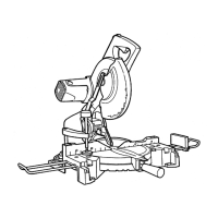
3. Lower limit position of saw blade when cutting a large workpiece
NOTE:
When cutting a workpiece exceeding 3-11/32" (85mm) in height in right-angle cutting or
2-3/16"(55mm) in left bevel angle cutting or 1-3/16" (30mm) in right bevel angle cutting,
adjust the lower limit position so that the base of the motor head (see Fig. 9) will not come
in contact with the workpiece.
To adjust the lower limit position of the saw blade, follow the procedures (1) to (3) shown in Fig. 10-a.
(1) Loosen the 8mm wing nut so that the 8mm depth adjustment bolt can be turned by hand.
(2) Lower the motor head, and thru the 8mm depth adjustment bolt by hand and make adjustments so that
there can be a clearance of 3/32" to 1/8" (2mm to 3mm) between the lower limit position of the motor head
and the top of the workpiece at the saw blade’s lower limit position (where the head of the 8mm depth
adjustment bolt contacts the gear case.
(3) After adjustment, turn the 8mm wing nut until it contacts the Hinge (see Fig. 10), and fully tighten it.
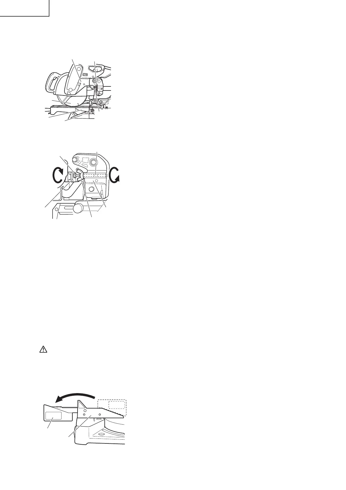
4. Confi rmation for use of sub fence
WARNING: In the case of left bevel cutting, turn the sub fence counterclockwise. Unless it is
turned counterclockwise, the main body or saw blade may contact the sub fence,
resulting in an injury.
This power tool is Equipped with a sub fence.
In the case of direct angle cutting and right bevel angle cutting, use the
sub fence. Then, you can realize stable cutting of the material with a
wide back face.
In the case of left bevel cutting, raise the sub fence up as illustrated in
Fig. 11 and then turn it counterclockwise.
Gear Case
Base
8mm Wing Nut
8mm Depth
Adjustment
Bolt
Saw Blade
Turntable
Fig. 9
8mm Depth
Adjustment Bolt
8mm Hexagon Socket
Set Screw
Turn
8mm Wing Nut
Loosen
Gear Case
Hinge
Fig. 10
Sub Fence
Left bevel angle cutting
Turn
Right bevel angle cutting
Direct angle cutting
Fence (B)
Fig. 11
0000BookC10FSH.indb140000BookC10FSH.indb14 2015/08/1015:19:162015/08/1015:19:16
 Loading...