ABOUT THE SYSTEM SYSTEM FRONT VIEW
1-10
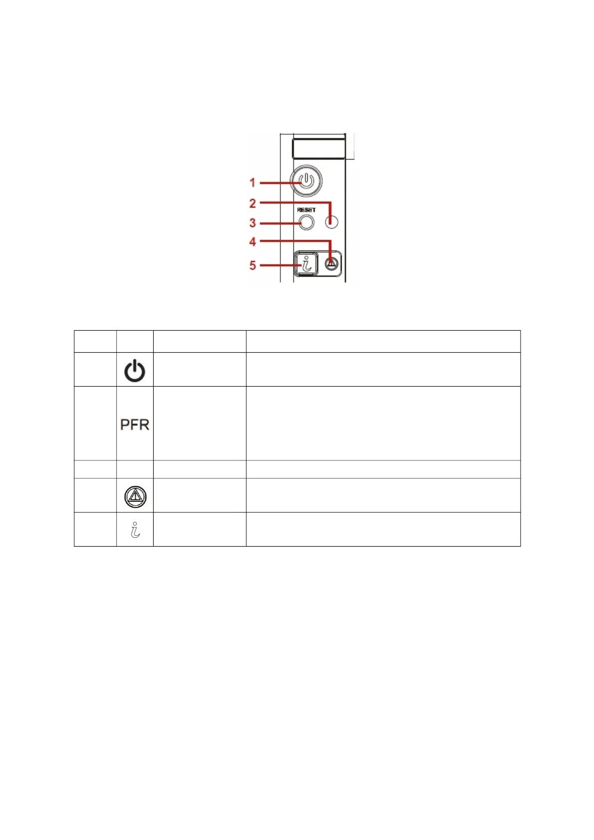
Front Control Panel (FCP)
For purposes of this procedure, the FCP is used for the numbering indicators.
Figure 1-3. Front Control Panel
Table 4: F
ront Control Panel Definition
NO. ICON NAME DESCRIPTION
1.
Power button with
LED
Power on / off
Blue on – S0 system power on; off – S5 system power off
2.
PFR Status LED
(
Only for certain
models)
Provides notification of PFR operation status
Off: Power Off/PFR Module is not installed
Green On: Authenticated
Amber On: Failed
Amber Blinking: Authentication/Recovery is executing in T-1
3. Reset button Soft reset system function
4. System Status LED
Provides critical and non-critical failure notification
Amber blinking – failed; Off – SEL cleared / good
5.
Identification but-
ton with LED
Toggles ID LED, activate ID LED to identify system
Blue blinking – Identifier on front and rear chassis; off – Normal.
 Loading...