ABOUT THE SYSTEM LED STATUS DESCRIPTIONS
1-15
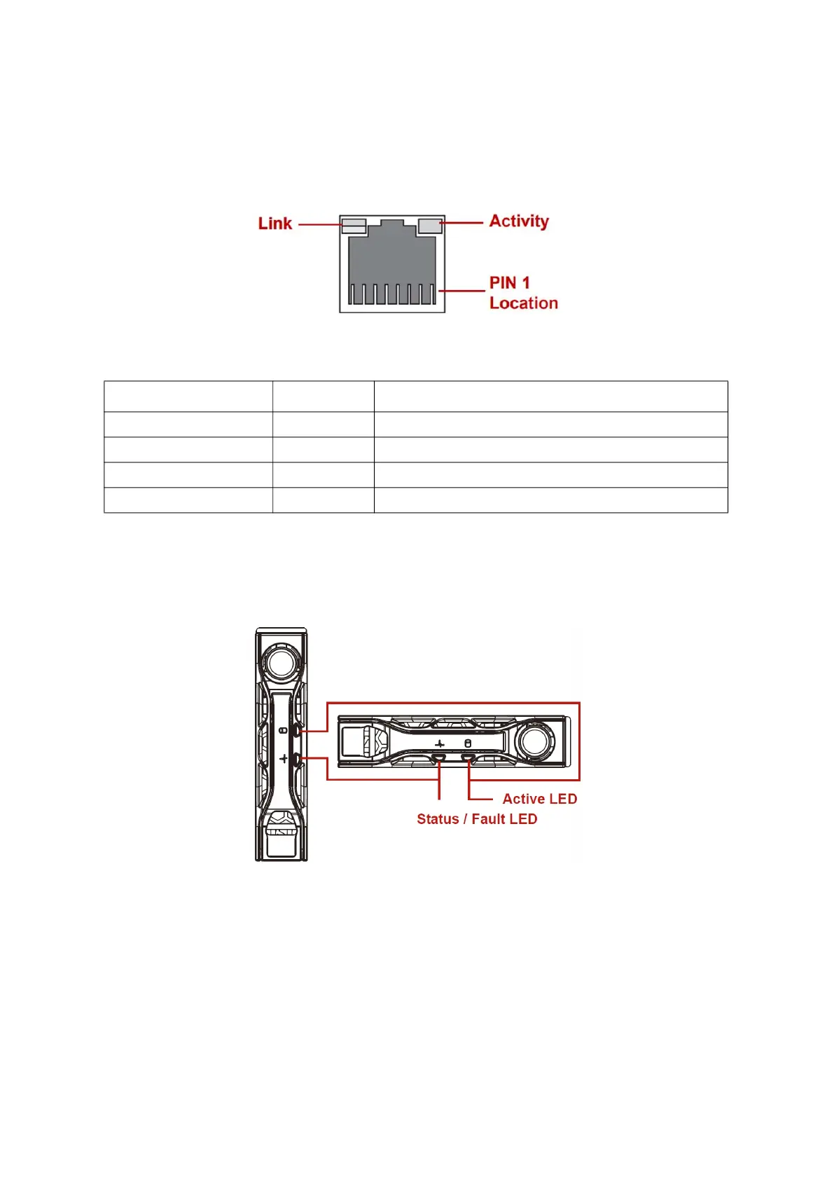
BMC Management Port LEDs
The system mainboard includes one dedicated RJ45 GbE management port. The RJ45 con-
nector has two built-in LEDs. See the following illustration and table for details.
Figure 1-9. GbE RJ45 Management
Table 11: R
J45 LED Descriptions
Storage Drive LED
Front 2.5" Storage Drive LED Status Behavior
Figure 1-10. 2.5" Storage Drive LED Identification
CONDITION LIINK ACTIVITY
Unplugged Off Off
1G active link On amber Blinking green
100M active link On green Blinking green
10M active link Off Blinking green
 Loading...