ABOUT THE SYSTEM SYSTEM REAR VIEW
1-12
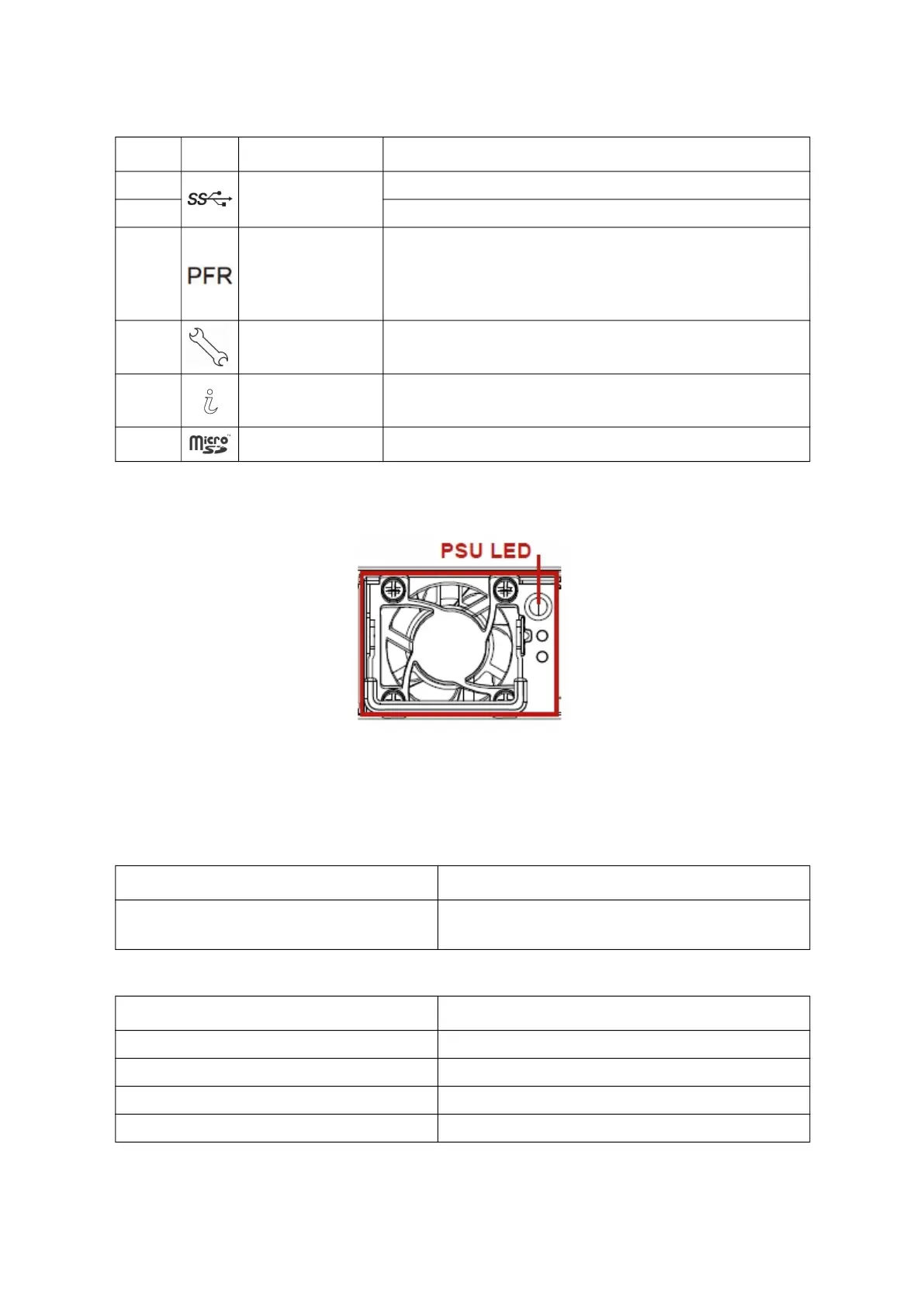
Power Sub-System
Figure 1-6. PSU to Mainboard Module Description
A single power supply unit (default) is supplied in the system. A secondary PSU is available
f
or redundancy functionality.
Table 7: P
ower Supply Units by Model
Table 8: P
ower Supply Unit LED
3.
USB 3.0 port
USB 1 port; connect to USB device
4. USB 0 port; connect to USB device
5.
PFR Status LED
(Only for certain
models)
Off: Power Off/PFR Module is not installed
Green On: Authenticated
Amber On: Failed
Amber Blinking: Authentication/Recovery is executing in T-1
6. Micro USB port Transmit in serial signal for debug or terminal concentrator
7. Identification LED Blue blinking - Identifier; Off - Normal
8. MicroSD slot Backup BMC SEL
PSU AC INPUT
2 x 1200W/1600W/2200W Titanium/Platinum
high efficiency redundant PSU
100-240VAC 50/60Hz, AC/HVDC support
PSU LED COLOR DESCRIPTION
Amber On PSU failure
Green On PSU good
Green Blinking at 0.5Hz PSU standby
Green Blinking at 2Hz PSU cold redundancy standby
Table 6: System Rear I/O Definition (Continued)
NO. ICON NAME DESCRIPTION
 Loading...