7
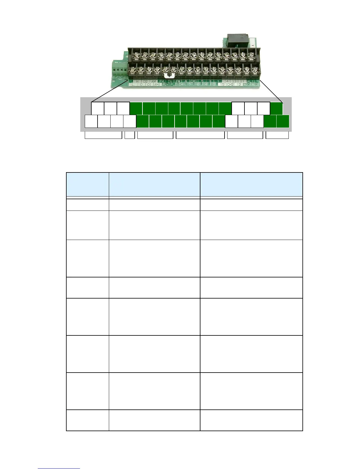
Control Circuit Terminals
Terminal
Name
Description Ratings and Notes
P24 +24V power for inputs 24VDC supply, 100 mA max.
CM1 +24V common Common for 24V supply,
FW, TH, inputs 1 to 8, and
FM. (Note: Do not ground)
PLC Common for logic inputs Common for input terminals
1 to 8, jumper to CM1 for
sinking, jumper to P24 for
sourcing
CM2 Common for logic outputs Common for output termi-
nals 11 to 15
1, 2, 3, 4,
5, 6, 7, 8
Intelligent (program-
mable) discrete logic
inputs
27VDC max. (use P24 or an
external supply referenced to
terminal CM1), 4.7kΩ input
impedance
FW Forward/stop command 27VDC max. (use P24 or an
external supply referenced to
terminal CM1), 4.7kΩ input
impedance
11, 12, 13,
14, 15
Intelligent (program-
mable) discrete logic
outputs
Open collector type, 50mA
max. ON state current, 27
VDC maximum Off state
voltage
TH Thermistor input Reference to CM1, min.
thermistor power 100mW
L O OI
P24
7
PLC
CM1
6 4 2
CM2 ALO
12
AL2
13
AL1
115 3 1
15
14
CM1
8
FWFM
AM
AMI
O2
H
TH
Analog
inputs
Analog
outputs
Power
Alarm
relay
Logic
inputs
Logic
outputs
 Loading...