ENGLISH
7.3 SETTING OF DIP SWITCHES AND RSW SWITCHES
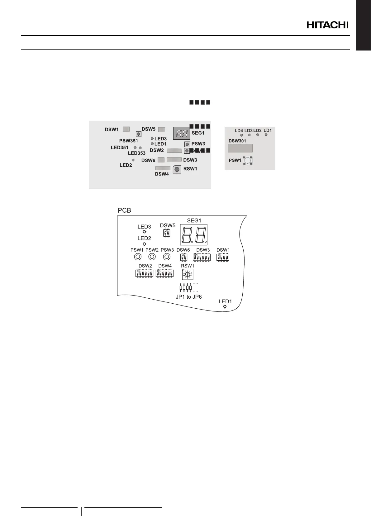
7.3.1 Outdoor unit
7.3.1.1 Location of DIP switches and rotary switches
The PCB in the outdoor unit is operating with DIP switches and push switches. The location is as follows:
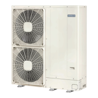
RAS-(2/2.5)WHVNP
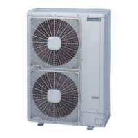
RAS-(3-10)WH(V)NPE
? NOTE
DIP-IPM or PCB2 (depending on model) has a DSW1. When pin number 1 is set to ON position, the electrical current detections is cancelled. Pin
number 1 should be to OFF position after electrical work.
ELECTRICAL AND CONTROL SETTINGS
PMML0335A rev.1 - 04/2016
99
 Loading...