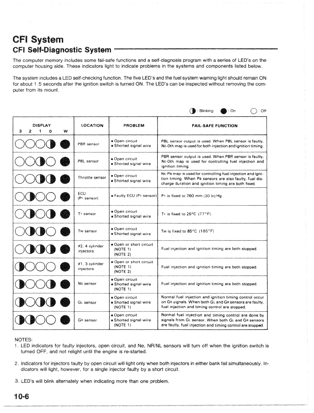
CFI System
Self-Diagnostic System
The
comp,utE~r
memory
includes
some
fail-safe
functions
and a self-diagnosis program with a
series
of
LED's
on
the
comp,utE~r
h~)uS,lng
side. These indicators to indicate nrclhll'!m!':
in
the
SV!~tAms
and components listed below.
The includes a LED
o:::.",lf."I,.,,,,,..,kin'l"I
function. The five LED's and the fueI6Y::Hem VlJlt;lm,inn
for
about
.5
seconds after
the
switch
is
turned
ON.
The LED's can be inspelcted
from its
mount
should remain
ON
ren10\lling the com-
():
Blinking • : On Off
DISPLAY
:3
2.
1 0 W
lOCATION
PROBLEM
FAil-SAFE FUNCTION
PBR
sensor
PBl
sensor
Throttle sensor
ECU
(1"1
sensor)
T1
sensor
Tw Sensor
#2. 4
cylinder
injectors
#1, 3 cylinder
injectors
()OOct
e Ns sensor
.. Open circUit
.. Shorted signal
wire
.. Open circuit
.. Shorted signal
wire
.. Open circuit
.. Shorted signal
wire
Faulty
ECU
(P1 sensorl
Open
circuit
.. Shorted signal
wire
.. Open circuit
.. Shorted signal
wire
.. Open or short
circuit
(NOTE
I}
(NOTE 2)
.. Open or short
circuit
(NOTE 1)
(NOTE 2)
.. Open circuit
.. Shorted signal
wire
(NOTE
1)
PBl
sensor
output
is used.
When
PBl
sensor is faulty.
NE-Oth
mllp
is used
for
bolh inteclion
lind
ignilion
liming.
PBR sensor
oulput
is used.
When
paR sensor is faulty,
NE-Oth map is used
for
controlling fuel injection
lind
ignition liming.
NE-Pa
map is used
for
controlling fuel and igni-
tion
timing.
When
PI!
sensors are also fuel dis-
charge
duration and ignition
timing
are both fixed.
1"1
is fixed to
760
mm
(30
in) Hg
Tl
is fixed to 25"C
(77°F)
.
Tw is fixed to 85°C
(185
0
F)
Fuel injection and ignition
timing
are both stopped.
Fuel
injection and Ignition
liming
are both stopped.
Fuel injeclion and
ignilion
timing
are both stopped.
()O()()
e
Gl
sensor
..Opan circuit
.. Shorted signal
wire
(NOTE
11
Normal fuel injeclion and
ignition
liming
control occur
on
GR
signals.
When
bolh
Gl
and
GR
sensors are faulty,
fuel injection and
timing
control are stopped.
()
GR
sensor
.. Open
circuit
.. Shorted signal
wire
(NOTE 1)
Normal
fuel
injection
and
timing
control
lire
done by
signals
from
GL
sensor.
When
both andGR sensors
are fuel
injection
and
timing
are stopped.
NOTES:
1.
LED
indicators for
turned and not
and NR/NL
sensors
will turn off when the
is ra-started,
switch is
In-
when
both
injE~ct,ors
in
either
bank
fail sirrluit:anElOusly
a short circuit.
open
circuit
wll!
however, for a
Indicators
fOr injElctlJrS
dicators will
LED's will blink altEII'nI:ltellv
when
indlcaiting more than one
prClblElm,
10-6
 Loading...