eFt System .
Camshaft
Angle
(GR,
Gl)
Sensors--------------
LED
Inspection
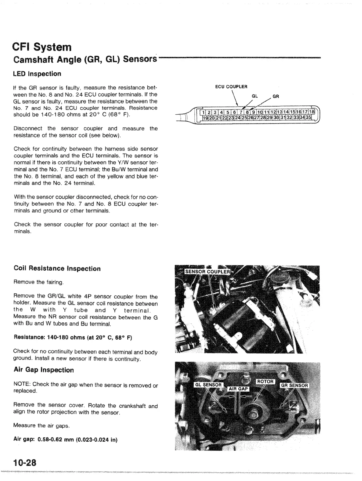
feu COUPLER
measure the
Disconnect the
sensor
resistance of the sensor coil
If the
GR
sensor is measure the resistance bet·
ween
the
No.8
and No.
24
ECU
terminals. If the
GL sensor
is measure the resistance between the
No.7
and No.
24
coupler terminals. Resistance
should be
140·180
ohms at
20
<>
C
Check for between
the harness side sensor
",.",nl
••
r terminals
and
the
ECU
terminals. The sensor is
normal if there is between the Y/W sensor ter-
minal
and
the No. 7
ECU
the Bu/W and
the
No. 8 and each
of
the and blue ter·
minals
and the No.
24
terminal.
With the sensor coupler check for no can-
between the No. 7
and
No. 8
ECU
ter·
minals and ground or other terminals.
Check
the sensor
I,;VUl.lt,;:"
minals.
for poor contact at the ter·
Coil Resistance Inspection
Remove the fairing.
Remove the GR/GL white 4P
sensor from the
holder. Measure the GL sensor coil resistance between
the
W
with
Y
tube
and
Y
terminal.
Measure the
NR
sensor coil between the G
with
Bu
and W tubes and Bu terminal.
Re~liiti~nce:
140-180 ohms
<at
20° 68°
F)
Check for no between each terminal and
Install a new sensor
if
there is
Air Gap Inspection
NOTE: Check the air gap when the sensor
is
removed or
Remove the sensor cover. Rotate the crankshaft and
the rotor
With
the sensor.
Measure the air gaps,
Air
gap: 0.58-0.62 mm (0.023-0.024
In)
10
..
28
 Loading...