Install the sensors
in
the reverse order of removal.
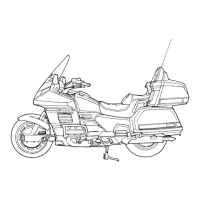
Remove
the white 4P sensor
COldo!!ers
from the GR/GL
CO!JOIl"lf
holder.
Remove the sensor cover. Remove the two bolts
and
remove the sensors.
Removalllnstallation
page 7-3).
be handled as a
coil from the frame
Remove
the
NOTE: The
and
GL sensors
matched
set
Install them
in
NOTE:
Inspel:::t
the air gap when the sensors or rotors are
page
1
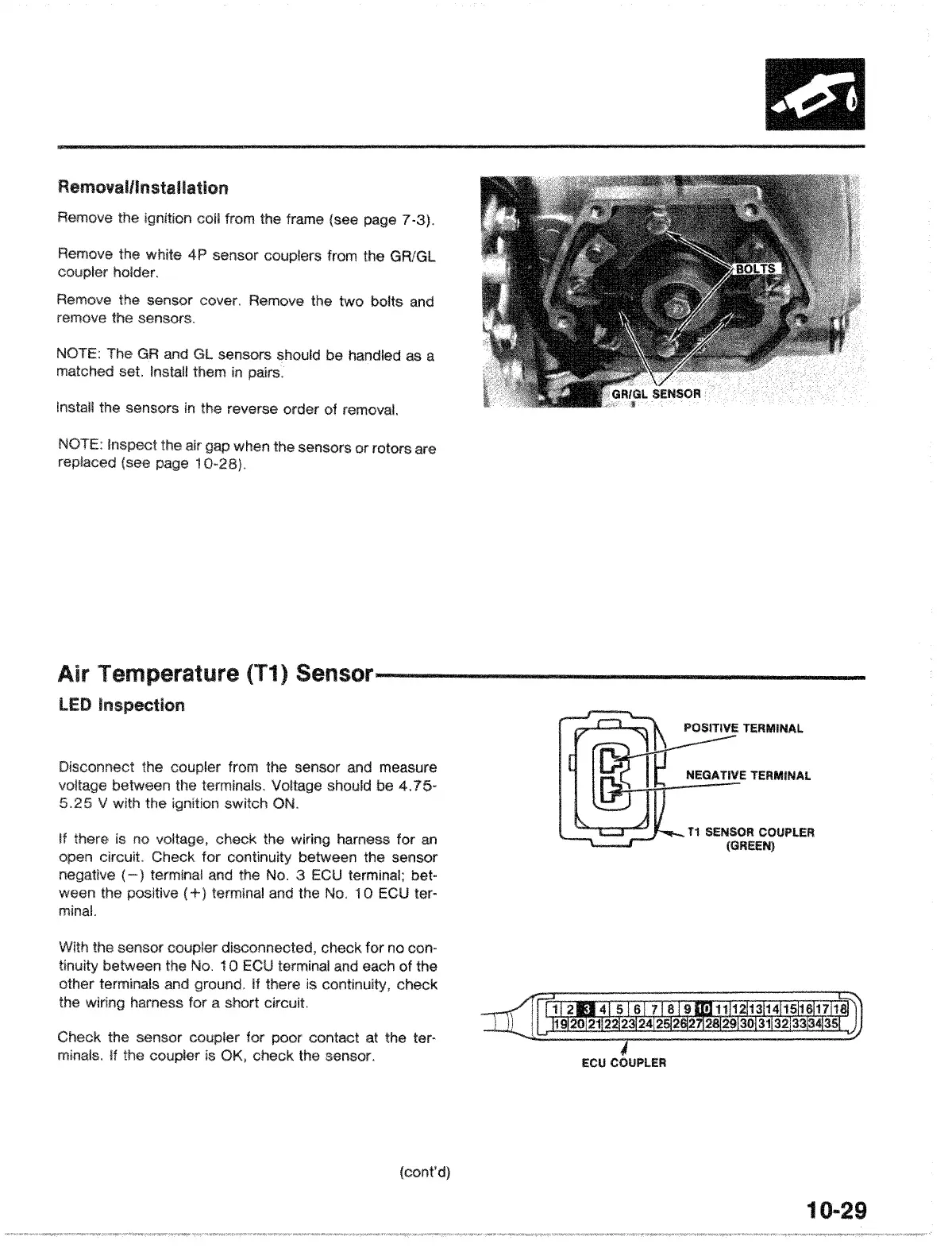
T1
SENSOR
COUPLER
(GREEN)
Disconnect the from the sensor and measure
voltl'icle between the terminals. should be
4.75-
5.25
V with the switch ON.
Air Temperature
(T1)
Sensor----------------
LED
Inspection
if
there is no check the harness for
an
open circuit. Check for continuity between the sensor
ne!gative
( terminal and the
No.
3
ECU
terminal; bet-
ween the terminal and the NO.1
a
ECU
ter-
minal.
With the sensor check for no con-
between
the
No.
10
ECU
terminal
and
each of the
other terminals and If there is check
the harness for a short circuit.
Check the sensor
COllph"r
for
poor contact at the ter-
minals. If the
is
check the sensor.
ECl!
COUPLER
10
..
29
 Loading...