 Loading...
Do you have a question about the Honda NX250 1989 and is the answer not in the manual?
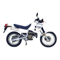
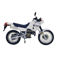
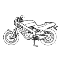
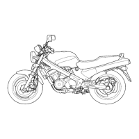
| Year | 1989 |
|---|---|
| Manufacturer | Honda |
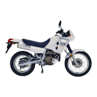
| Model | NX250 |
| Category | Dual-sport |
| Displacement | 249 cc |
| Compression Ratio | 11.0:1 |
| Ignition | CDI |
| Transmission | 6-speed |
| Final Drive | Chain |
| Front Suspension | Telescopic fork |
| Rear Suspension | Pro-Link single shock |
| Front Brake | Single disc |
| Rear Brake | Drum |
| Front Tire | 3.00-21 |
| Seat Height | 830 mm |
| Engine Type | Single cylinder, four-stroke |
| Bore x Stroke | 70.0 x 64.8 mm |
| Carburetion | Keihin |