HYDRAULIC BRAKE
INSPECTION
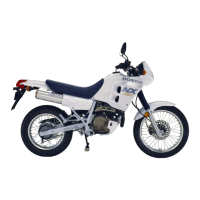
Check the primary and secondary cups for wear, deterioration
or damage.
Check the master cylinder and piston for scoring or other
dam-
age.
Measure the master cylinder inside diameter.
SERVICE
LIMIT;
11
05b mm
(0.4352
In)
Measure the master piston outside diameter.
SERVICE LIMIT: 10.945 mm
(0.4309
in)
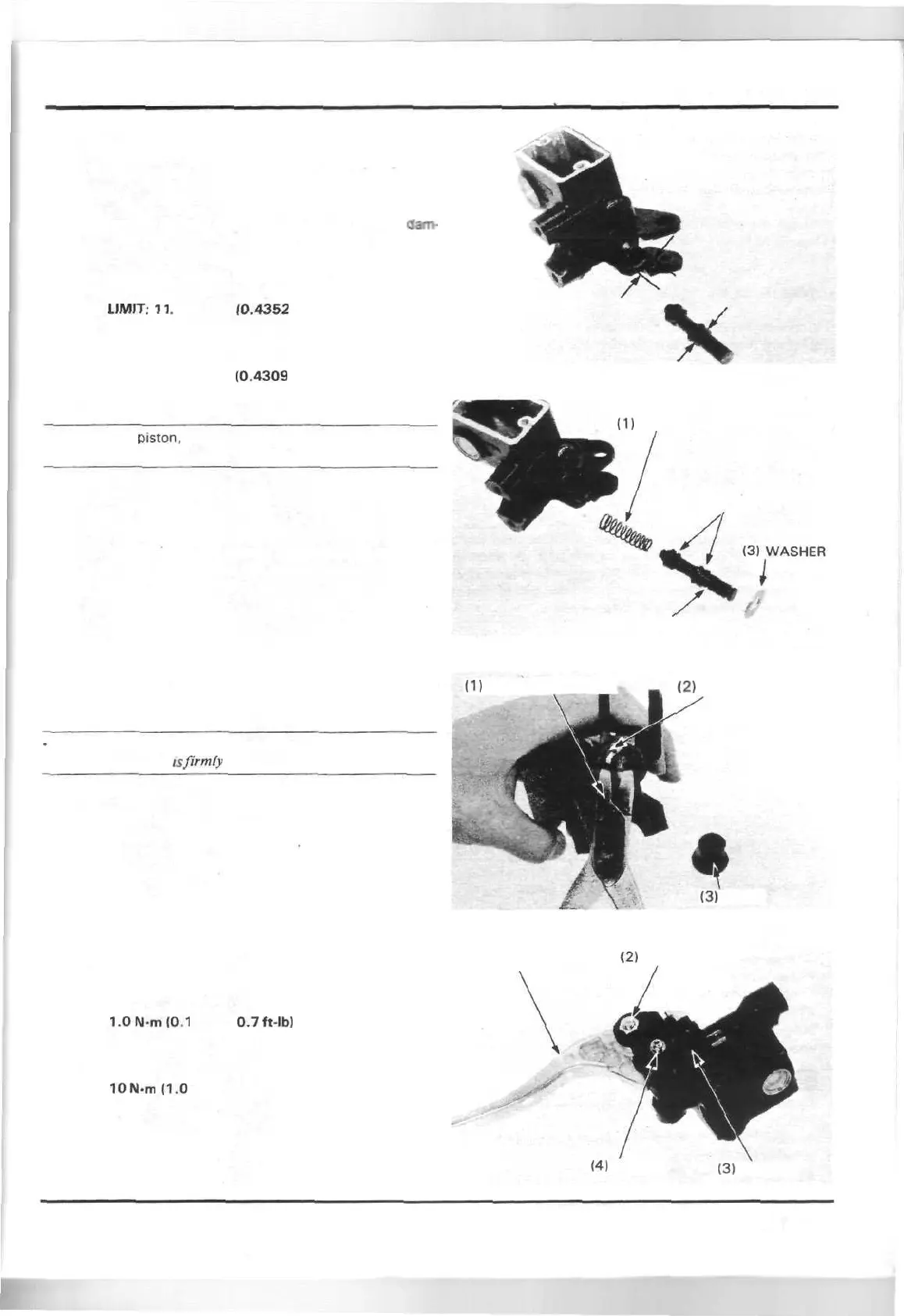
NOTE
• The master
piston,
piston cups and spring must be replaced
as a set.
ASSEMBLY
Coat the master piston and primary and secondary cups with
clean brake fluid, then install the spring, master piston and
washer into the master cylinder.
(1)
SPRING
(2) PISTON CUPS
(4) MASTER PISTON
Install the snap ring and piston boot.
CAUTION
Do not allow the lips of the cups to turn inside out and be cer-
tain the snap ring
is firmly
seated in the groove.
(1)
SNAP RING PLIERS
TOOL:
Snap ring pliers 07914-3230001 or
equivalent commercially
available in U.S.A.
(2)
SNAP RING
(3)
BOOT
Install the brake light switch.
Tighten the screw to the specified torque.
TORQUE:
1.0N-m(0.1
kg-m,
0.7
ft-lb}
Install the brake lever and tighten the pivot nut.
TORQUE:
10
N-m
11.0
kg-m, 7 ft-lb)
(1) LEVER
(2)
PIVOT NUT
(41
SCREW
(3)
SWITCH
14-7
 Loading...