ECS Series Emergency Communication System Installation Manual 151455
4-14
4.4.2 Mounting the ECS-50W
The ECS-50W is equipped with a separate enclosure. It is also available in a black cabinet. (P/N ECS-
50WB). Refer to Section 3.1 when selecting a mounting location for the ECS-50W.
The panel should be accessible to main drop wiring runs. It should be mounted as close to the center
of the building as possible and located within a secured area, but should be accessible for testing and
service.
Mount the control panel cabinet so it is firmly secured to the wall surface. When mounting on concrete,
especially when moisture is expected, attach a piece of ¾” plywood to the concrete surface and then
attach the cabinet to the plywood. Also mount any other modules to the plywood.
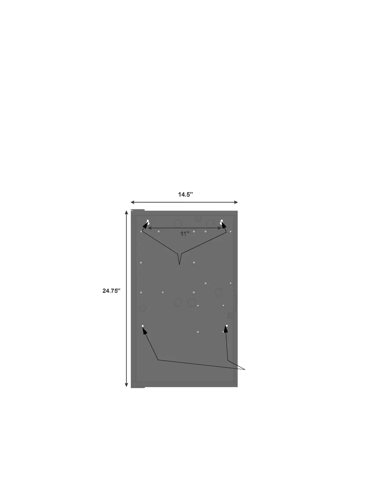
The cabinet can be surface or flush-mounted. If you will be flush-mounting the cabinet, the hole for the
enclosure should be 14.5" W x 24¾” H x 3-7/16” D (36.8cm W x 62.9cm H x 8.73cm D). Do not flush-
mount in a wall designated as a fire break. The Outside dimensions of the cabinet are 16" W x 26½” H
x 4-1/8” D (40.64cm W x 66.68cm H x 10.48cm D).
Follow these steps to properly mount the cabinet.
1. On the mounting surface install two screws level with each other 11" apart.
Figure 4-22 Cabinet Flush Mount Dimensions and Mounting Hole Locations
2. Install the cabinet onto the two mounting screws and tighten the screws.
3. Insert two screws into the two bottom mounting holes.
Key Holes
Bottom Mounting
Holes

 Loading...


