ECS Device Installation 151455
4-17
4.4.4.1 Wiring Lengths
Note: The above table assumes a uniform distribution of the speakers, and that a max of 20% voltage drop on the
last speaker is allowed.
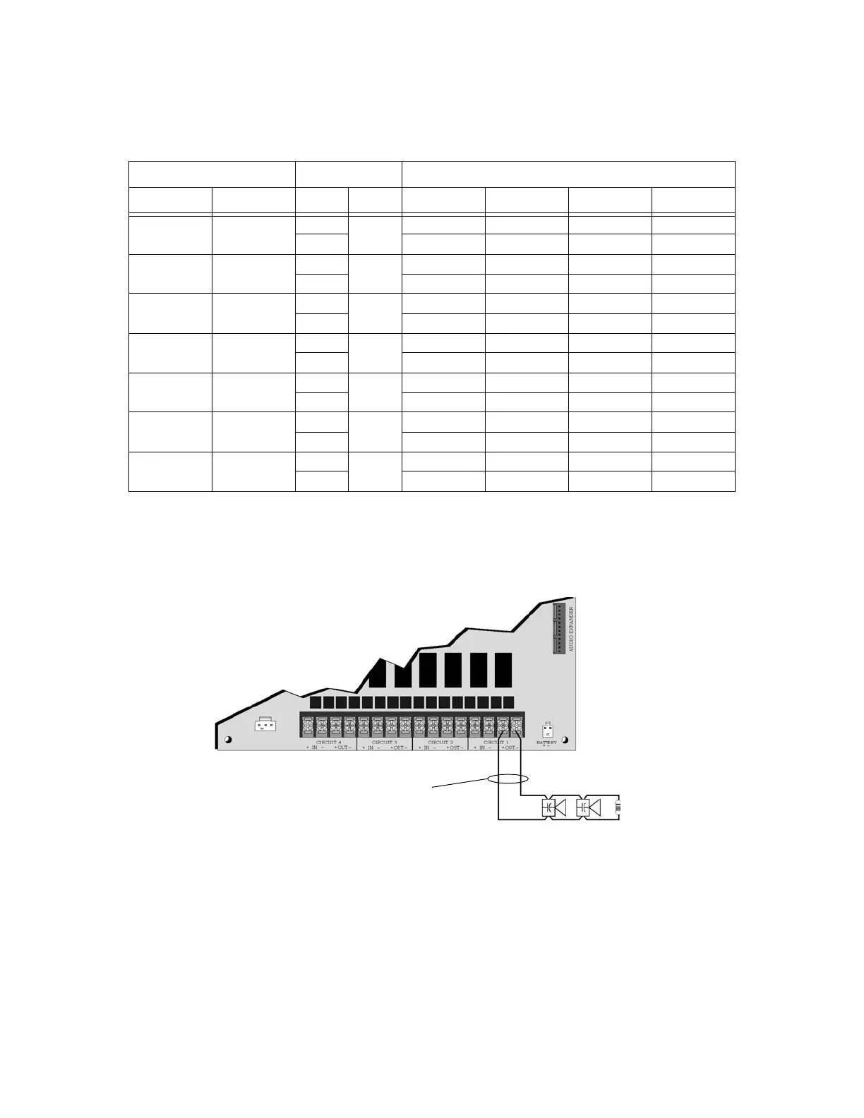
4.4.4.2 Class B Speaker Configuration
Figure 4-24 illustrates how to wire speakers to the control panel using Class B supervision.
Figure 4-24 Class B Speaker Configuration
Table 4-2
Number Of Speakers Total Load Wire Distance in Feet
@1/2 W @1 W Vrms Watts 18 AWG 16 AWG 14 AWG 12 AWG
10 5 25Vrms 5W 3900 6200 9860 15680
70Vrms 25000 39700 63200 100520
20 10 25Vrms 10W 2125 3380 5375 8540
70Vrms 15200 24150 38400 61100
30 15 25Vrms 15W 1460 2320 3690 5870
70Vrms 11000 17500 27800 44200
40 20 25Vrms 20W 1100 1750 2780 4420
70Vrms 8500 13510 21500 34175
52 26 25Vrms 26W 760 1200 1920 3050
70Vrms 6100 9700 15400 24520
80 40 25Vrms 40W 550 875 1390 2200
70Vrms 4100 6500 10360 16480
100 50 25Vrms 50W 450 715 1130 1800
70Vrms 3500 5560 8850 14070
15kΩ EOL
UL Listed
Supervised
Power Limited

 Loading...


