ECS Series Emergency Communication System Installation Manual 151455
4-42
4.7.10 Calculating Current Draw and Standby Battery
This section helps you determine the current draw and standby battery needs for your installation (18
Ampere Hours maximum will fit in cabinet). Complete the remaining instructions in Table 4-6.
Batteries larger than 18 AH will not fit in the main control cabinet, and must be housed in the RBB
Accessory Battery Cabinet. Maximum of 35 amp hr for the system.
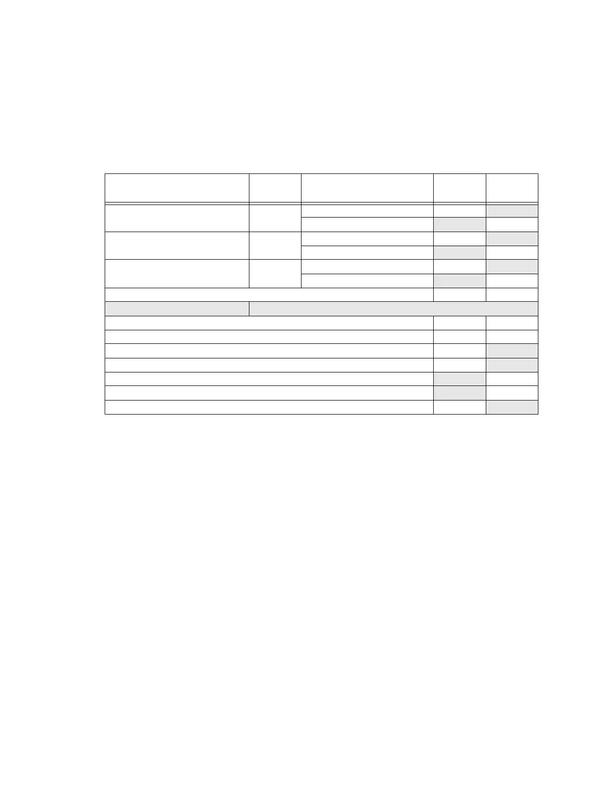
Table 4-6: Current Draw ECS-125W
Device
No. of
Devices
Current Per Device
Standby
Current
Alarm
Current
ECS-125W 120V 1 Standby: 375 mA 375 mA
Alarm: 700 mA 700 mA
ECS-125W 240V 1 Standby: mA mA
Alarm: mA mA
ECS-CE4 0 or 1 Standby: 20 mA 20 mA
Alarm (All Channels): 180 mA 180 mA
A Current Subtotals: mA mA
Notification Devices Refer to device manual for number of devices and current ratings.
B Current Subtotals: mA mA
C Total current rating of all devices in system (Line B) X 0.001 A A
D Number of standby hours (24 or 60 for NFPA 72) H
E Multiply line C (standby current) and D:Total standby AH AH
F Alarm sounding period in hours (For example, 5 minutes = 0.0833 hours): H
G Multiply line C (alarm current) and F:Total alarm AH
AH
H Add lines E and G (AH = Ampere Hours):Total AH required AH

 Loading...


