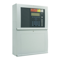
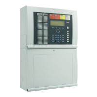
Fire Alarm Control Panel IQ8Control C / M
FB 798951.10.GB0 / 04.15 73
7.1.6 essernet
®
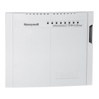
micro module (Part No. 784840 / 784840.10 and 784841 / 784841.10)
The essernet
®
micro module must be placed on the micro module slot of the Basic module. There for it is required
to set the corresponding jumpers on the Basic module to configure the terminals for the essernet
®
micro module.
essernet
micro module 62,5 kBd (Part No. 784840)
essernet
micro module 500 kBd (Part No. 784841)
S2
LED
essernet
®
module
red
yellow
green
0
1
2
3
4
5
6
7
8
9
0
1
2
3
4
5
6
7
8
9
X1
S1
X4 X5
Fig. 64: essernet
®
micro module (Part No. 784840 / 784841)
or
essernet
micro module 62,5 kBd (Part No. 784840.10)
essernet
micro module 500 kBd (Part No. 784841.10)
S1
LED
essernet
®
module
red
yellow
green
0
1
2
3
4
5
6
7
8
9
0
1
2
3
4
5
6
7
8
9
X1
S2
X4 X5
Fig. 65: essernet
®
micro module (Part No. 784840.10 / 784841.10)
System conformity according to EN 54-13 requires increased sensitivity in the monitoring of line
connections. This has been appropriately taken into consideration in the essernet
®
modules (Part
No. 784840.10 and 784841.10).
The software of the modules remains fully compatible with earlier versions.
If a new essernet
®
module is installed into an existing system or if an additional fire alarm control
panel with an essernet
®
module (Part No. 784840.10 or 784841.10) is integrated into an existing
network, there may be - depending on the configurations of these line connections - an increase in
the number of fault messages.
Common reasons for such faults include corroded connection points and loose terminal connections
that were still within the tolerance ranges of the earlier versions of the essernet
®
modules.
If you encounter such fault messages, the entire line network must be carefully inspected.
Compliance with EN 54-13 requires that the greatest of care be taken when setting up such
networks, which have a significant impact on the manner of line installation and the connection
types.

 Loading...


