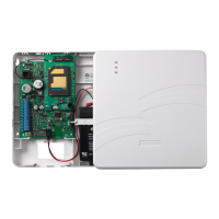
Section 2: Mounting and Wiring
2-3
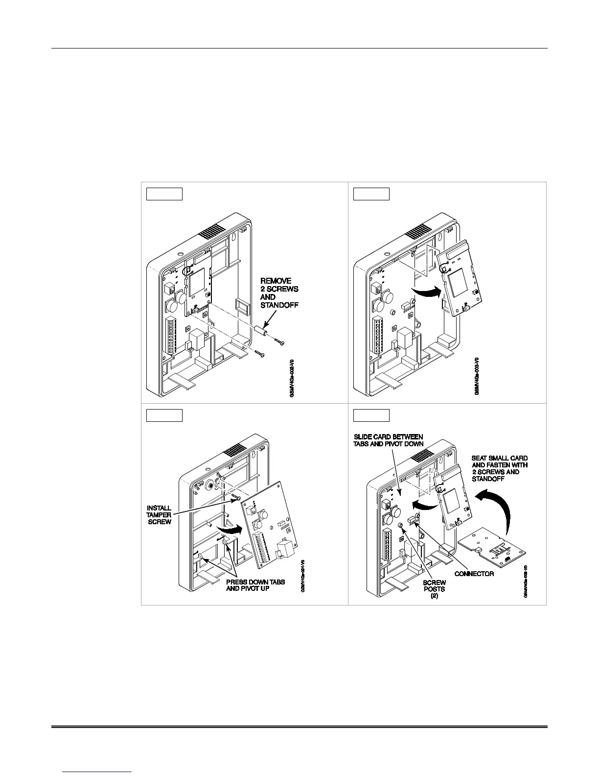
Mounting Procedure, GSMVCN4G (with rear tamper switch)
For Canadian installations where the rear tamper switch is used, this procedure requires the
removal of the printed circuit boards and installation of the tamper screw.
1. Remove the two mounting screws, and standoff from the daughter card, as shown in
Step A below.
2. Remove the daughter card by pivoting upward, as shown in Step B below.
3. Remove the lower printed circuit board by pushing down on the lower tabs and pivoting
the board upward, as shown in Step C below.
STEP A STEP B
STEP C STEP D
4. Locate the case back over selected mounting position such that the opening in the case
back is aligned with the wire/cable opening on the mounting surface.
5. Pass the wires/cable through the opening in the case back, or route through the
removable knockouts located on the back cover.
6. Secure the case back to the mounting surface using four screws (supplied).
7. Install the tamper screw (provided), as shown in Step C above.
 Loading...