GSMV4G/GSMVCN4G Installation and Setup Guide
2-6
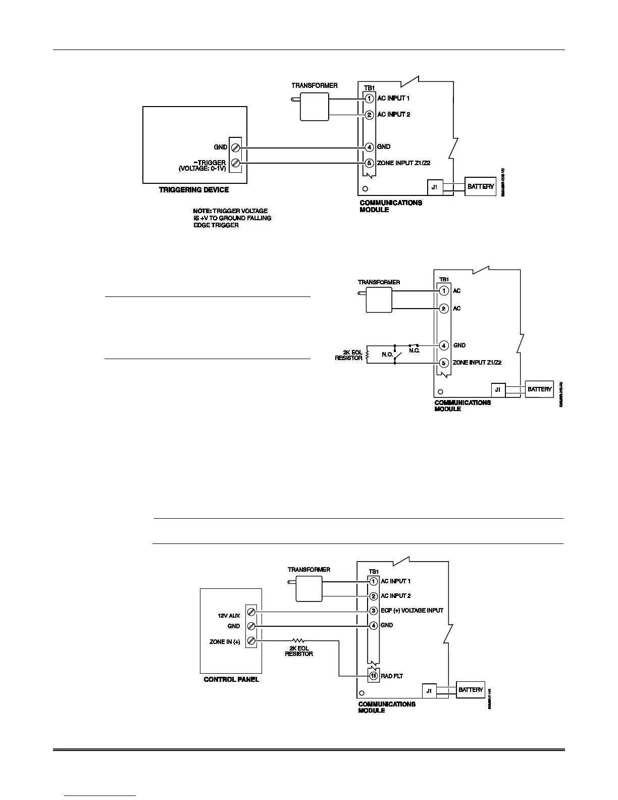
Wiring the Zone 1 Input for a Ground (-V) Trigger
Wiring the Zone 1 Input for EOL Supervised N.O./N.C. Triggers
Wiring the Fault Relay
You may wire and program the communicator's fault output trigger for fail-safe mode (see
the question "FLT REL ON Y/N").
To sense a communicator fault at the control panel, see the figure below and make the
following connections. Include the proper EOL resistor required by the control panel.
A 24 hour supervisory zone must be assigned on the control panel, with the communicator's fault
relay wired to that zone.
Wiring the Fault Relay to a Control Panel Zone for Normally Closed Fault
UL
• Zones should use EOL resistors, and be pro-
grammed as V+ Inverted or V– Inverted
operation such that a cut line results in an
alarm.
• Do not use zones 1 and 2 for UL installations.
 Loading...